A-Eberle OR-Z4C0-S1503LT Retrofit-Ready Power Quality Controller: Compatible Upgrade for OR-Z4C0 Series Control Systems
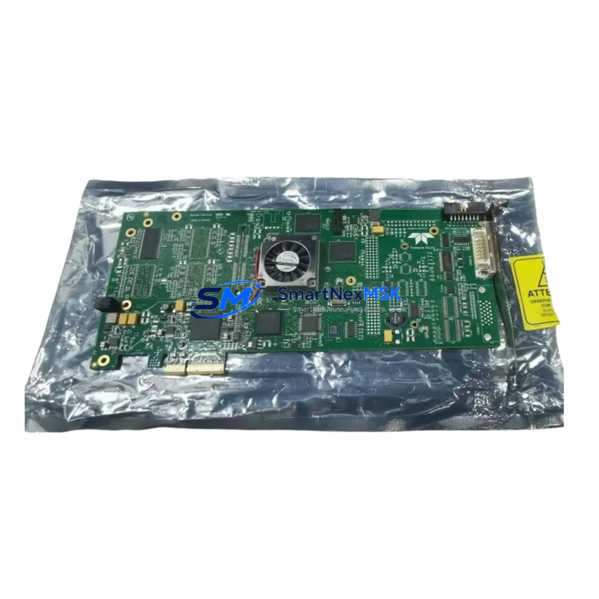
The A-Eberle OR-Z4C0-S1503LT is a retrofit-ready power quality controller engineered as a direct functional replacement and upgrade path for legacy OR-Z4C0 series installations. Designed for industrial facilities operating aging reactive power compensation systems, this unit addresses the growing challenge of sourcing discontinued components while maintaining grid stability, power factor correction, and harmonic management across existing control cabinet infrastructure.
Whether your plant is running a decades-old reactive power compensation bank or managing a multi-feeder substation with legacy A-Eberle OR-Z4C0 controllers, the OR-Z4C0-S1503LT provides a validated upgrade route that preserves your existing wiring topology, terminal block assignments, and communication architecture — minimizing engineering rework and reducing total retrofit cost.
Upgrade Compatibility Table
| Parameter | OR-Z4C0 (Legacy) | OR-Z4C0-S1503LT (Retrofit) |
|---|---|---|
| Mounting Format | DIN Rail / Panel Mount | DIN Rail / Panel Mount (identical footprint) |
| Supply Voltage | 110–240 V AC | 110–240 V AC (universal input) |
| Measurement Input | CT secondary 1A / 5A | CT secondary 1A / 5A (selectable) |
| Output Relay Steps | Up to 12 steps | Up to 15 steps (backward compatible) |
| Communication Interface | RS-485 / Modbus RTU (optional) | RS-485 Modbus RTU (standard) |
| Display | LCD, 2-line | LCD, 4-line with backlight |
| Target Power Factor Setting | 0.80–1.00 (cos φ) | 0.70–1.00 (cos φ), extended range |
| Harmonic Detection | Basic THD monitoring | Enhanced THD + individual harmonic analysis |
| Installation Requirement | Standard terminal block wiring | Same terminal layout — no rewiring required |
| Retrofit Recommendation | — | Direct drop-in replacement; verify CT ratio and step count |
| Commissioning Focus | Manual step calibration | Auto-detection + manual override available |
| Warranty | — | 12-Month Warranty (SMARTNEXMSK) |
Retrofit Planning for Existing Automation Systems
Successful integration of the OR-Z4C0-S1503LT into an existing reactive power compensation system begins with a thorough audit of the control cabinet. Before removing the legacy OR-Z4C0 unit, engineers should document the current CT secondary wiring — typically routed through a terminal block strip to the controller’s current input terminals — and confirm whether the installation uses 1A or 5A CT secondaries, as the OR-Z4C0-S1503LT supports both via internal DIP switch selection.
Power supply capacity within the cabinet must be verified. The OR-Z4C0-S1503LT draws its auxiliary supply from the same 110–240 V AC bus used by the legacy controller, but if the cabinet also houses an A-Eberle PQS series power quality sensor or a third-party harmonic filter controller, the total auxiliary load should be recalculated to ensure the existing DIN rail power supply module — often a 24 V DC SITOP or Phoenix Contact unit — is not overloaded.
Terminal block wiring on the OR-Z4C0-S1503LT follows the same logical grouping as the OR-Z4C0: voltage measurement inputs (L1, L2, L3, N), current transformer input (I1), relay output contacts (K1–K12 or K1–K15 depending on step configuration), and RS-485 communication terminals (A, B, GND). If the existing installation uses a Modbus RTU network to relay power factor data to a SCADA system or an energy management gateway, the RS-485 bus address and baud rate settings from the legacy controller should be recorded and replicated on the OR-Z4C0-S1503LT during commissioning.
For cabinets that include capacitor bank contactors — such as Schneider Electric TeSys or Siemens 3RT series — the relay output wiring from the OR-Z4C0-S1503LT connects directly to the existing contactor coil circuits without modification. If the system uses thyristor switching modules (TSM) for fast-switching capacitor steps, confirm that the OR-Z4C0-S1503LT’s relay output timing is compatible with the TSM’s minimum pulse width requirement.
In multi-panel installations where the OR-Z4C0 communicates with an HMI panel — such as a Weintek MT series or Siemens SIMATIC HMI — the Modbus register map of the OR-Z4C0-S1503LT should be compared against the existing HMI screen configuration. Most standard power factor and reactive power registers are preserved, but any custom diagnostic registers used in the HMI project may require remapping. This is typically a minor adjustment in the HMI programming software and does not require hardware changes.
Where the legacy system includes an A-Eberle REG-D or REG-DA voltage regulator on the same communication bus, the OR-Z4C0-S1503LT can coexist on the RS-485 network as a separate node, provided each device is assigned a unique Modbus address. This is particularly relevant in substation retrofit projects where both voltage regulation and reactive power compensation are managed from a single SCADA interface.
If the retrofit scope extends to replacing the capacitor bank itself — for example, upgrading from fixed-step capacitors to a detuned capacitor bank with series reactors — the OR-Z4C0-S1503LT’s extended step count (up to 15 steps) and enhanced harmonic detection capability make it well-suited to manage the new bank configuration without requiring a higher-tier controller.
Downtime Control During System Migration
Minimizing production downtime during the OR-Z4C0-S1503LT retrofit is achievable through careful pre-staging and a structured hot-swap procedure. Before the scheduled maintenance window, the replacement unit should be pre-configured on the bench: CT ratio, target power factor (cos φ), step switching delay, and Modbus address should all be programmed and verified against the legacy controller’s parameter sheet.
During the switchover, the capacitor bank should be taken offline by opening the main contactor or isolator feeding the compensation panel. The legacy OR-Z4C0 can then be de-energized, disconnected from the terminal block, and removed from the DIN rail. Because the OR-Z4C0-S1503LT shares the same physical footprint and terminal layout, the replacement unit can be mounted and wired within the same maintenance window — typically 30 to 60 minutes for a single-panel installation.
Once wired, the OR-Z4C0-S1503LT should be powered up in manual mode first, allowing the engineer to verify voltage and current measurement readings before enabling automatic step switching. The auto-detection routine will identify the number of connected capacitor steps and their reactive power values, cross-referencing against the programmed target cos φ. Only after this verification should the system be returned to automatic operation.
Original program logic in any upstream PLC — such as a Siemens S7-300 or Allen-Bradley MicroLogix managing the compensation panel’s interlock circuit — does not require modification, as the OR-Z4C0-S1503LT’s relay output behavior and Modbus register structure are designed to be backward compatible with the OR-Z4C0 command interface. This preserves the existing ladder logic and prevents the need for a PLC program download during the live retrofit window.
For sites where continuous power factor correction is critical — such as facilities with utility penalty clauses for low power factor — a temporary bypass contactor can be used to hold the capacitor bank at a fixed switching state during the controller swap, maintaining reactive power compensation throughout the maintenance window and avoiding any penalty-triggering power factor excursions.
Retrofit Support FAQ
Q1: Is the OR-Z4C0-S1503LT a direct drop-in replacement for the OR-Z4C0?
Yes. The OR-Z4C0-S1503LT is designed as a functional replacement for the OR-Z4C0 series. It shares the same DIN rail mounting format, terminal block layout, and auxiliary supply voltage range. No rewiring is required in standard installations. Verify the CT secondary rating (1A or 5A) and set the internal DIP switch accordingly before installation.
Q2: Will my existing Modbus RTU communication setup work with the OR-Z4C0-S1503LT?
Yes. The OR-Z4C0-S1503LT supports RS-485 Modbus RTU as a standard feature. Configure the Modbus address and baud rate to match the legacy controller’s settings. Core power factor, reactive power, and step status registers are preserved for backward compatibility with existing SCADA and HMI configurations.
Q3: What commissioning steps are required after installation?
After mounting and wiring, power up the unit in manual mode and verify voltage and current measurement accuracy. Run the auto-detection routine to identify connected capacitor steps. Set the target cos φ, switching delay, and CT ratio. Test relay output operation by manually triggering each step. Confirm Modbus communication with the upstream SCADA or HMI before returning the system to automatic operation.
Q4: What warranty and pre-shipment testing does SMARTNEXMSK provide?
Every OR-Z4C0-S1503LT unit supplied by SMARTNEXMSK undergoes pre-shipment functional testing, including power-up verification, relay output actuation, and communication interface check. All units are covered by a 12-month warranty from the date of shipment. In-stock units are available for same-week dispatch to support urgent retrofit and breakdown replacement requirements.
© 2026 SMARTNEXMSK. All rights reserved.
Original Source: https://smartnexmsk.com
Contact: sales@smartnexmsk.com | +86 18259474341