ABB Bailey L700743A3-10 Retrofit-Ready DCS Cable for INFI 90 Control Systems
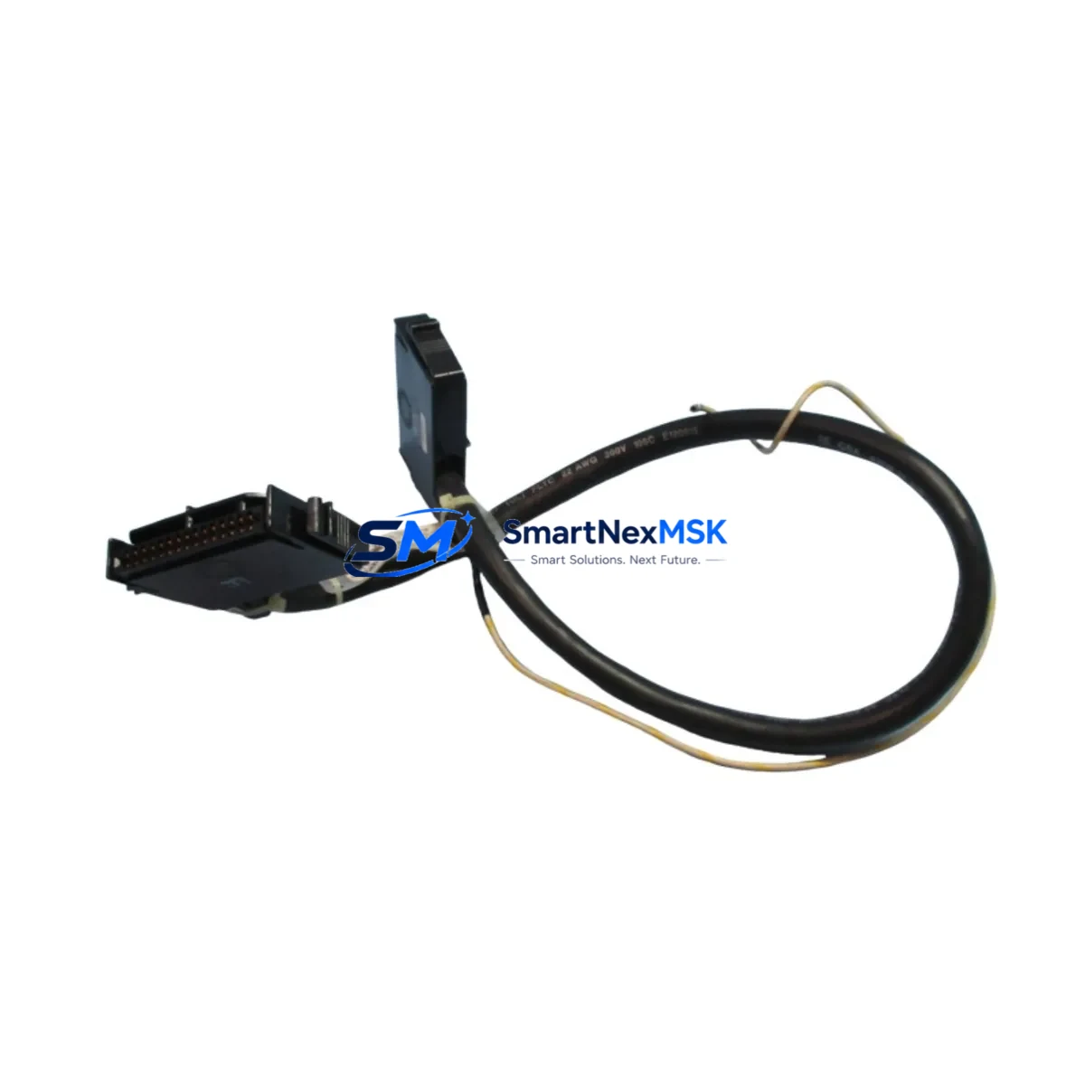
The ABB Bailey L700743A3-10 is a purpose-built analog terminal cable assembly designed for seamless integration into INFI 90 distributed control system architectures. As legacy INFI 90 installations approach end-of-life or require expansion, sourcing a verified, drop-in compatible cable assembly is critical to maintaining system integrity without triggering a full platform migration. SMARTNEXMSK stocks the L700743A3-10 as a retrofit-ready replacement, pre-tested and ready for immediate deployment in existing control cabinets.
Whether you are replacing a degraded cable on an aging INFI 90 Network 90 node, upgrading wiring harnesses during a partial DCS modernization, or restoring a system after an unplanned failure, the L700743A3-10 provides the electrical and mechanical compatibility required to resume operations with minimal downtime. The cable assembly is manufactured to flame-retardant specifications and is compatible with the standard terminal block pinout used across the INFI 90 analog I/O subsystem.
Upgrade Compatibility Table
| Parameter | Details |
|---|---|
| SKU / Part Number | L700743A3-10 |
| Brand / OEM | ABB Bailey |
| Compatible Platform | INFI 90 (Network 90 / INFI 90 Open) |
| Cable Type | Analog Terminal Cable Assembly |
| Connector Interface | Standard INFI 90 analog I/O terminal block |
| Installation Requirement | No backplane modification required; direct plug-in replacement |
| Communication Compatibility | Compatible with INFI 90 analog signal loops (4–20 mA, ±10 V) |
| Replacement Recommendation | Direct drop-in for degraded or discontinued L700743A3-10 assemblies |
| Commissioning Notes | Verify terminal polarity and shield grounding before energizing; no firmware change required |
| Warranty | 12-Month Warranty — covers manufacturing defects and electrical performance |
| Origin | China (CN) |
| Weight | 680 g |
Retrofit Planning for Existing Automation Systems
Retrofitting an INFI 90 system requires careful coordination across multiple hardware layers. The L700743A3-10 cable assembly connects analog field devices to the INFI 90 analog input/output modules — typically the IMASI03 or IMASO01 analog I/O cards mounted in the IMMFP12 or IMMFP02 multi-function processor rack. Before replacing the cable, engineers should verify that the associated NTAI05 or NTAI09 termination unit is in serviceable condition, as a degraded termination unit can cause signal errors even after a cable swap.
In systems where the INFI 90 backplane has been partially upgraded to support INFI 90 Open or hybrid Symphony Plus architecture, the L700743A3-10 remains compatible with the legacy analog I/O slots without requiring re-addressing or module reconfiguration. However, if the migration path involves replacing the IMMFP12 controller with a PM866 or PM891 AC 800M processor module, the cable assembly and termination strategy must be re-evaluated against the new I/O bus architecture.
Power supply integrity is another key consideration. The INFI 90 analog subsystem draws regulated 24 VDC from the cabinet power rail, typically supplied by an IMPS10 or IMPS02 power supply module. Before installing the L700743A3-10, confirm that the power supply output is within tolerance and that the rail voltage has not drifted due to aging capacitors or load imbalance. A marginal power supply can cause intermittent analog signal errors that are difficult to distinguish from cable faults.
For systems that include INFI-NET or INFI 90 Controlway communication links, the cable replacement does not affect the network topology. However, if the retrofit is part of a broader migration to PROFIBUS DP or Modbus RTU field communication, the analog terminal cable may be superseded by a digital field bus interface module, and the L700743A3-10 should be retained as a spare for any remaining hardwired analog loops. Programming compatibility with the existing INFI 90 Control Builder or Composer engineering workstation is maintained, as the cable replacement does not alter the I/O module address or channel configuration stored in the controller database.
HMI screens configured in INFI 90 OIS (Operator Interface Station) or migrated to a modern System 800xA graphics environment will continue to display analog values correctly after the cable swap, provided the field device calibration and engineering unit scaling remain unchanged. If the retrofit includes replacing the NTAI05 termination unit alongside the L700743A3-10 cable, re-verify the channel zero and span calibration at the field device before returning the loop to automatic control.
Downtime Control During System Migration
Minimizing unplanned downtime is the primary concern for any INFI 90 cable replacement or retrofit activity. SMARTNEXMSK recommends the following approach to protect original program logic and maintain field control continuity during the L700743A3-10 swap:
- Pre-stage the replacement cable before the maintenance window. Verify part number, connector type, and cable length against the installed assembly to avoid last-minute mismatches.
- Place affected analog loops in manual mode at the INFI 90 OIS or DCS console before disconnecting the cable. This prevents the controller from responding to signal loss with spurious output commands.
- Document terminal wiring with photographs or a wiring diagram before disconnection. The L700743A3-10 uses a multi-conductor arrangement; incorrect re-termination can reverse signal polarity or introduce ground loops.
- Perform a cold-swap with the I/O module de-energized where possible. If a hot-swap is required, confirm that the INFI 90 analog module supports live insertion without generating a fault alarm that could propagate to the safety interlock system.
- Restore and verify each analog channel individually after reconnection. Compare live field readings against known reference values before returning loops to automatic control. A calibrated loop calibrator connected at the field terminal can confirm signal integrity end-to-end.
- Retain the removed cable assembly as a temporary spare until the replacement has been confirmed stable through at least one full process cycle.
With proper pre-planning, the physical cable swap can typically be completed within a 30–60 minute maintenance window, keeping production impact to a minimum.
Retrofit Support FAQ
Q1: Is the L700743A3-10 a direct replacement for the original ABB Bailey part, or are there wiring differences I need to account for?
A: The L700743A3-10 supplied by SMARTNEXMSK is a direct form-fit-function replacement for the original ABB Bailey assembly. The connector pinout, cable length, and termination style are identical to the OEM specification. No wiring modifications are required at the INFI 90 termination unit or field junction box.
Q2: Can this cable be used in a partially upgraded INFI 90 system that now includes Symphony Plus modules?
A: Yes. The L700743A3-10 is compatible with legacy INFI 90 analog I/O slots that remain in service alongside Symphony Plus or AC 800M controller upgrades. As long as the analog I/O module (e.g., IMASI03) and its associated termination unit (e.g., NTAI05) are retained in the upgraded rack, the cable assembly will function without modification.
Q3: What commissioning checks should be performed after installing the replacement cable?
A: After installation, verify terminal polarity, confirm shield grounding continuity to the cabinet earth bar, and perform a loop check using a calibrated 4–20 mA source at the field terminal. Confirm that the INFI 90 controller reads the expected engineering unit value at both zero and full-scale input before returning the loop to automatic mode.
Q4: What warranty coverage is provided, and what does it include?
A: All L700743A3-10 cable assemblies shipped by SMARTNEXMSK carry a 12-month warranty covering manufacturing defects, connector integrity, and electrical performance under normal operating conditions. Each unit undergoes pre-shipment functional testing. In the event of a warranty claim, SMARTNEXMSK will arrange replacement or repair at no additional cost. Contact sales@smartnexmsk.com with your order reference and a description of the fault.
© 2026 SMARTNEXMSK. All rights reserved.
Original Source: https://smartnexmsk.com
Contact: sales@smartnexmsk.com | +86 18259474341