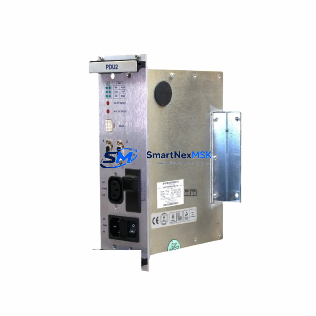
ADEPT 10338-53100 Retrofit-Ready Amplifier Module for 10338 Series Control Systems
The ADEPT 10338-53100 is a retrofit-ready amplifier module engineered for seamless integration into existing 10338 series control architectures. As industrial automation systems age and original equipment manufacturers discontinue legacy components, the 10338-53100 provides a verified drop-in replacement path that preserves existing wiring configurations, backplane interfaces, and program logic — minimizing engineering rework and unplanned downtime during system modernization projects.
Whether you are managing a planned control cabinet upgrade, responding to an emergency spare-parts shortage, or executing a phased migration from an end-of-life automation platform, the 10338-53100 is stocked, tested, and ready for immediate dispatch. Each unit undergoes functional verification prior to shipment and is covered by a 12-month warranty against manufacturing defects and operational failure.
Upgrade Compatibility Table
| Parameter | Details |
|---|---|
| SKU / Part Number | 10338-53100 |
| Brand | ADEPT Technology |
| Compatible Series | ADEPT 10338 Series Control Systems |
| Module Type | Amplifier Module |
| Backplane Interface | Compatible with 10338 series rack and backplane connectors |
| Installation Requirement | Direct slot replacement; no mechanical modification required |
| Communication Compatibility | Maintains existing signal and communication protocol assignments |
| Terminal Wiring | Retains original terminal block layout; verify conductor gauge and torque spec |
| Replacement Recommendation | Suitable for direct replacement of discontinued 10338-53100 units |
| Commissioning Notes | Verify module address assignment and I/O mapping after installation |
| Warranty | 12-Month Warranty — covers manufacturing defects and functional failure |
| Origin | China (CN) |
Retrofit Planning for Existing Automation Systems
Successful retrofit of the ADEPT 10338-53100 begins with a thorough pre-installation audit of the existing control cabinet. Engineers should document the current power supply capacity — typically a 24 VDC or 120 VAC rail — to confirm that the replacement amplifier module’s power draw falls within the available headroom of the existing power supply module. In many 10338 series installations, the power supply module is shared across multiple I/O and amplifier slots; adding or replacing a module without verifying total load can cause nuisance tripping or undervoltage faults.
Terminal block wiring should be photographed and labeled before removal of the legacy module. The 10338-53100 preserves the original terminal layout, but wire ferrule condition, conductor insulation integrity, and terminal torque values should be inspected and corrected as part of the retrofit. This is particularly important in installations where the original wiring dates back more than a decade.
The backplane interface of the 10338 series rack accepts the 10338-53100 without adapter hardware. However, engineers should inspect the rack’s backplane connector pins for oxidation or mechanical damage before seating the replacement module. In multi-slot racks, the module address is typically set via DIP switch or software configuration within the associated programming environment — confirm the address assignment matches the original module’s slot mapping to avoid I/O conflicts.
For systems that include a dedicated communication module — such as a Profibus DP interface card, DeviceNet scanner, or Ethernet/IP adapter — the amplifier module’s signal outputs must be verified against the communication module’s configured I/O table. Any mismatch between the physical module address and the software-defined I/O map will result in fault conditions at startup. This verification step is especially critical in systems where the HMI panel displays real-time process values derived from the amplifier module’s analog outputs.
In installations where the 10338-53100 interfaces with servo drives or motion controllers, the amplifier’s gain settings, feedback signal type (resolver, encoder, or tachometer), and enable logic must be confirmed against the original commissioning documentation. Systems that also incorporate a dedicated I/O expansion module or a remote I/O rack should have their network topology reviewed to ensure the replacement module does not alter scan cycle timing or introduce communication latency.
Programming cable access is recommended during commissioning. A direct connection to the controller — whether via RS-232 serial cable, USB programming adapter, or Ethernet port — allows the commissioning engineer to monitor module status registers, verify analog input/output scaling, and confirm that the control program’s function blocks are addressing the replacement module correctly. Where the original program logic includes module-specific diagnostic routines, these should be tested under simulated load conditions before returning the system to full production.
Downtime Control During System Migration
Minimizing production downtime during an amplifier module replacement requires a structured pre-outage preparation protocol. Before the scheduled maintenance window, the commissioning team should export a full backup of the controller program, including all data tables, function block configurations, and HMI screen tag bindings. This backup serves as the recovery baseline if the replacement module requires parameter re-entry or if the control program must be reloaded following a power cycle.
Where the process allows, a staged cutover approach is preferred. The replacement 10338-53100 can be pre-configured on a bench test setup — using a compatible rack and power supply — to verify module response, analog output scaling, and communication handshake before the unit is installed in the live control cabinet. This bench validation step typically reduces in-cabinet commissioning time to under 30 minutes for experienced engineers.
During the actual module swap, the control system should be placed in a safe hold state, with all field devices confirmed in their fail-safe positions. After the 10338-53100 is seated and the cabinet is re-energized, the controller’s diagnostic display or programming software should be used to confirm module recognition before enabling field outputs. HMI screens should be monitored for alarm conditions during the first production cycle following the replacement to confirm that all analog values and status indicators are reading correctly.
For facilities operating continuous processes where even brief outages carry significant cost, a hot-standby or redundant controller configuration — if supported by the existing platform — should be evaluated as part of the broader modernization plan. The 10338-53100’s compatibility with the existing 10338 series architecture means it can be integrated into redundant configurations without requiring changes to the primary control program structure.
Retrofit Support FAQ
Q1: Is the ADEPT 10338-53100 a direct replacement for the original discontinued unit?
Yes. The 10338-53100 is a verified replacement for the original ADEPT 10338-53100 amplifier module. It maintains the same backplane connector, terminal block layout, and module address scheme as the original, allowing direct slot-for-slot substitution without mechanical modification to the existing rack or cabinet.
Q2: What commissioning steps are required after installation?
After seating the replacement module, engineers should confirm the module address assignment via DIP switch or software configuration, verify analog I/O scaling against the original commissioning records, and perform a controlled startup with the controller’s diagnostic tools active. HMI screen values and communication module I/O tables should be checked during the first production cycle to confirm correct operation.
Q3: Will the replacement module affect existing terminal wiring or communication links?
The 10338-53100 preserves the original terminal block layout, so existing field wiring can be reconnected without modification in most installations. Communication links — including Profibus, DeviceNet, or Ethernet/IP connections routed through a dedicated communication module — should be verified against the controller’s I/O configuration table after replacement to confirm that signal assignments remain intact.
Q4: What does the 12-month warranty cover, and how is it processed?
The 12-month warranty covers manufacturing defects and functional failure under normal operating conditions. Each unit is functionally tested prior to shipment. In the event of a warranty claim, contact our sales team with the order reference and a description of the fault. Replacement or repair will be arranged promptly to minimize impact on your production schedule.
© 2026 SMARTNEXMSK. All rights reserved.
Original Source: https://smartnexmsk.com
Contact: sales@smartnexmsk.com | +86 18259474341