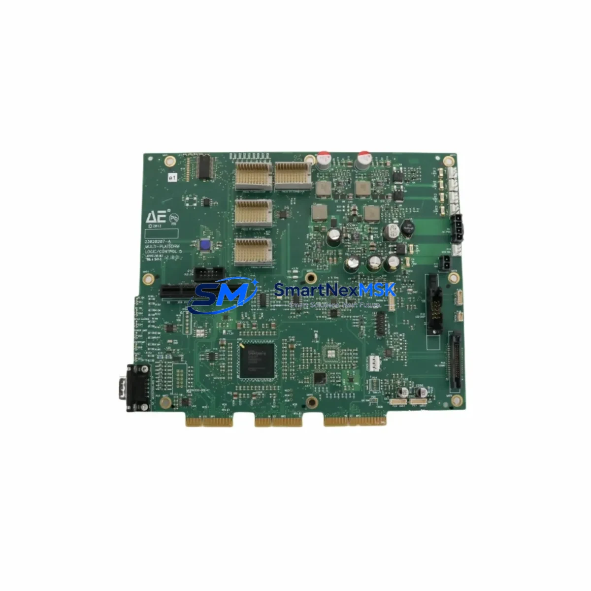
ADVANCED 23020207-A Retrofit-Ready Logic Control Module: Compatible Modernization for Legacy Control Systems
The ADVANCED 23020207-A is a retrofit-ready logic control module engineered to serve as a direct replacement and functional upgrade for aging automation infrastructure. Whether your facility is decommissioning an end-of-life controller platform, recovering from an unplanned failure, or executing a planned control cabinet modernization, the 23020207-A provides a reliable, specification-matched solution that minimizes engineering rework and accelerates return to production.
This module carries cross-reference part numbers 0200-35100 and 0040-03062, which are commonly referenced in legacy system documentation, MRO procurement records, and OEM service manuals. Procurement teams and controls engineers can source this unit with confidence knowing it aligns with the original design intent of the installed base.
Upgrade Compatibility Table
| Parameter | Details |
|---|---|
| Primary SKU | 23020207-A |
| Cross-Reference P/N | 0200-35100 / 0040-03062 |
| Module Type | Logic Control Module |
| Brand / Manufacturer | ADVANCED |
| Country of Origin | China (CN) |
| Installation Interface | Backplane / rack-mount; confirm slot pitch and bus connector type against existing chassis before installation |
| Communication Compatibility | Verify protocol stack (Modbus RTU/TCP, PROFIBUS DP, or proprietary bus) against existing network topology prior to commissioning |
| Replacement Recommendation | Suitable for direct swap in compatible ADVANCED control platforms; verify firmware revision and I/O addressing before power-up |
| Commissioning Notes | Confirm module address DIP switch settings, terminal wiring polarity, and power rail voltage (typically 24 VDC) before energizing |
| Warranty | 12-Month Warranty — covers manufacturing defects under normal operating conditions |
| Pre-Shipment Testing | Each unit undergoes functional verification and outgoing quality inspection before dispatch |
Retrofit Planning for Existing Automation Systems
A successful retrofit begins well before the replacement module arrives on site. When integrating the ADVANCED 23020207-A into an existing control architecture, engineers should audit the full control cabinet bill of materials to identify interdependent components that may require simultaneous attention.
In many legacy installations, the logic control module operates in close coordination with a dedicated power supply module that feeds the backplane bus. If the existing power supply is undersized or approaching end of service life, it is advisable to evaluate its output capacity against the combined load of the 23020207-A and any co-installed I/O modules. Replacing the logic module while leaving a marginal power supply in service is a common source of intermittent faults post-retrofit.
The backplane or rack chassis itself deserves careful inspection. Connector pins on the bus interface can suffer oxidation or mechanical wear after years of service, and a new logic module will not resolve contact resistance issues originating in the rack. In systems using modular rack assemblies, it is worth confirming that the chassis slot assignment and module addressing scheme are correctly configured before the first power-up cycle.
Terminal wiring is another critical checkpoint. Many older installations use field wiring that was terminated to a specific I/O module’s screw terminal block or removable connector. When the 23020207-A is installed as a replacement, the field wiring must be verified against the updated I/O map. If the system previously used a discrete input module or analog output module with a different channel-to-terminal mapping, the wiring schedule must be reconciled before commissioning.
Communication infrastructure is equally important. Systems that rely on a serial communication module for Modbus RTU or RS-485 fieldbus connectivity must confirm that the new logic module’s communication port configuration — baud rate, parity, stop bits, and station address — matches the existing network parameters. In installations that have migrated partially to Ethernet-based protocols, a gateway module or protocol converter may already be present in the cabinet; the 23020207-A must be confirmed compatible with that communication bridge.
HMI screens and SCADA tag databases are often overlooked during hardware replacement projects. If the original logic module used a specific memory address range for data exchange with an operator panel or supervisory system, the replacement module must be configured to maintain those address assignments. Failure to do so will result in HMI display errors or loss of process visibility immediately after restart.
Programming cable compatibility is a practical concern during the commissioning phase. Older ADVANCED platforms may require a proprietary programming cable or USB-to-serial adapter to connect a laptop running the configuration software. Ensuring the correct programming cable and software version are available on site before the maintenance window begins prevents unnecessary delays.
Finally, consider the broader system context: if the control cabinet also houses a remote I/O expansion module, a motion control axis module, or a safety relay module, each of these components should be functionally verified after the logic module replacement to confirm that the system-level behavior is intact.
Downtime Control During System Migration
Minimizing unplanned downtime is the primary operational objective in any control system retrofit. The ADVANCED 23020207-A is stocked and available for immediate dispatch, which eliminates the lead-time risk that is common with OEM-sourced spare parts for discontinued or end-of-life modules.
Before the maintenance window opens, the existing PLC or DCS program should be backed up to an offline storage medium. This backup must include the full project file — not just the compiled binary — so that the program logic can be reviewed, modified if necessary, and re-downloaded to the replacement module. If the original program was created in a legacy version of the manufacturer’s programming software, confirm that the current software version can open and compile the project without errors before the scheduled outage begins.
A structured pre-shutdown checklist should cover: confirmation of the backup program file integrity, documentation of all current module configuration parameters (I/O addresses, communication settings, module-specific function block parameters), photographic record of terminal wiring, and verification that all necessary tools and replacement components are physically present at the work site.
During the swap, the field wiring should remain connected to the terminal block or connector wherever possible, with only the module itself being exchanged. This approach preserves the wiring integrity and reduces the risk of re-termination errors. After the new 23020207-A is seated in the rack and secured, the program download should be performed before energizing field outputs, allowing a dry-run verification of the logic execution and I/O addressing before live process signals are engaged.
Post-commissioning, a structured functional test covering all critical I/O points, communication links, and HMI data exchange should be completed and documented before the system is returned to automatic operation. This test record also serves as the baseline for the 12-month warranty period, confirming the installation date and initial operating condition of the replacement module.
Retrofit Support FAQ
Q1: Is the ADVANCED 23020207-A a direct drop-in replacement for the original module?
The 23020207-A is designed as a form-fit-function replacement for compatible ADVANCED control platform installations. Before installation, verify that the backplane connector type, slot pitch, power supply voltage, and firmware revision requirements match your existing system. Cross-reference part numbers 0200-35100 and 0040-03062 can be used to confirm compatibility against your original system documentation.
Q2: What commissioning steps are required after installing the replacement module?
After physical installation, confirm module address settings (DIP switches or software-configured station address), re-download the backed-up program, verify I/O channel mapping against the field wiring schedule, and test all communication links to connected HMI panels and network devices. A full I/O functional test should be completed before returning the system to automatic control mode.
Q3: How is wiring compatibility verified before the replacement module arrives?
Document the existing terminal wiring using the original system schematic and a photographic record of the installed wiring. Compare the terminal block layout and I/O channel assignments of the 23020207-A against the original module’s wiring diagram. If the terminal connector is a removable plug-in type, confirm that the connector pitch and pin count are identical before proceeding.
Q4: What does the 12-month warranty cover, and how is it activated?
The 12-month warranty covers manufacturing defects and functional failures under normal operating conditions. It is activated from the date of shipment. Each unit is subject to pre-shipment functional verification and outgoing quality inspection. To initiate a warranty claim, contact our technical support team with the order reference, installation date, and a description of the observed fault. Warranty does not cover damage resulting from incorrect installation, overvoltage, or environmental conditions outside the module’s rated specifications.
© 2026 SMARTNEXMSK. All rights reserved.
Original Source: https://smartnexmsk.com
Contact: sales@smartnexmsk.com | +86 18259474341