AERA FC-985C Retrofit-Ready Mass Flow Controller for FC-985CT-BF Series Control Systems
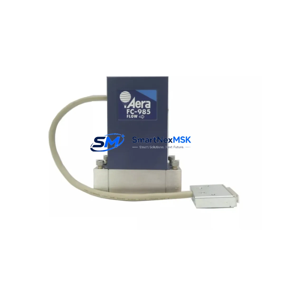
The AERA FC-985C (SKU: FC-985C : AR 100 SCCM TC FC-985CT-BF 1155820 SQ158) is a precision retrofit-ready mass flow controller engineered for seamless compatibility with legacy FC-985CT-BF series process control systems. Designed for Argon gas service at 100 SCCM full-scale range, this unit delivers a direct drop-in upgrade path for semiconductor fabrication, thin-film deposition, and specialty gas process lines where the original FC-985CT-BF has reached end-of-life or is no longer available through standard supply channels.
As OEM production of the FC-985CT-BF has been discontinued, facilities relying on this platform face increasing pressure to source qualified replacement units that preserve process repeatability without requiring full system redesign. The FC-985C addresses this challenge by maintaining electrical interface compatibility with the standard D-Sub 15-pin analog connector used across the FC-985CT-BF family, supporting both 0–5 VDC and 4–20 mA command and feedback signal formats. Engineers performing retrofit planning should verify the existing wiring harness pinout against the FC-985C interface specification prior to installation, particularly for units originally configured with custom setpoint scaling or valve override functions.
Every unit shipped by SMARTNEXMSK undergoes full functional verification including zero-point calibration, span calibration at rated flow, valve leak-by test, and response time measurement. Units are serialized and traceable to calibration records. A 12-month warranty covering manufacturing defects and calibration drift is included with every shipment.
Upgrade Compatibility Table
| Parameter | FC-985CT-BF (Legacy) | FC-985C (Retrofit Unit) |
|---|---|---|
| Gas Service | Argon (Ar) | Argon (Ar) |
| Full-Scale Range | 100 SCCM | 100 SCCM |
| Signal Interface | 0–5 VDC / 4–20 mA | 0–5 VDC / 4–20 mA |
| Electrical Connector | D-Sub 15-pin | D-Sub 15-pin (verify pinout) |
| Mounting / Installation | Surface mount, inline | Surface mount, inline (drop-in) |
| Communication Protocol | Analog (standard) | Analog (standard) |
| OEM Status | Discontinued | Available — in stock |
| Calibration | Factory (expired) | Fresh calibration, traceable |
| Commissioning Note | — | Verify zero/span after installation |
| Warranty | — | 12-Month Warranty included |
Retrofit Planning for Existing Automation Systems
Replacing an FC-985CT-BF in a live process line requires a structured approach to avoid introducing process drift or unplanned downtime. Before removing the legacy unit, technicians should document the current setpoint command voltage or current signal level, the actual flow reading from the host MFC controller or gas panel display, and the valve drive state. Many facilities running FC-985CT-BF units integrate them into gas delivery panels managed by a programmable logic controller (PLC) or a dedicated MFC controller chassis — common platforms include multi-channel analog I/O cards and RS-232 or RS-485 serial communication interfaces used in older gas panel architectures.
During the physical swap, confirm that the upstream pneumatic shut-off valve and downstream pressure regulator are isolated before disconnecting the legacy unit. The FC-985C uses the same body dimensions and port thread specification as the FC-985CT-BF, so no adapter fittings are required in standard installations. After mechanical installation, reconnect the signal harness and verify that the power supply rail — typically +15 VDC and −15 VDC for analog MFC circuits — is within specification before applying power. Facilities using a gas panel interlock relay board should confirm that the interlock logic recognizes the new unit’s power-on state signal before enabling flow.
For systems where the FC-985CT-BF was networked through a DeviceNet or PROFIBUS gateway module, note that the FC-985C operates on a standard analog interface and does not natively support fieldbus protocols. If the existing architecture relies on digital communication for flow data logging or recipe management, an analog-to-digital signal converter module or a dedicated MFC interface card may be required to maintain data continuity. Consult the host system’s I/O mapping documentation to confirm channel address assignments before re-enabling automated recipe execution.
Facilities upgrading multiple MFC positions simultaneously should also audit the condition of associated mass flow totalizer modules, gas line filter assemblies, and check valve cartridges in the same gas circuit. Replacing only the MFC while leaving aged ancillary components in service can introduce flow instability that is incorrectly attributed to the new unit during commissioning. A complete gas circuit audit prior to retrofit reduces the risk of repeat service calls and protects the 12-month warranty coverage on the FC-985C.
Downtime Control During System Migration
Minimizing production downtime during an MFC retrofit requires pre-staging the replacement unit and completing all documentation and verification steps before the maintenance window opens. SMARTNEXMSK ships the FC-985C with a calibration certificate and a pre-installation checklist that covers power supply verification, connector pinout confirmation, and post-installation zero/span check procedure. Having this documentation reviewed by the process engineer before the scheduled maintenance window allows the technician to complete the physical swap and functional verification within a single shift.
For facilities where the FC-985CT-BF is part of a multi-zone gas delivery system, consider staging the replacement during a scheduled preventive maintenance cycle rather than waiting for a failure event. Unplanned MFC failures in argon service lines can affect deposition uniformity across multiple process chambers simultaneously, making recovery time significantly longer than a planned swap. Maintaining one FC-985C as a cold standby spare in the facility’s MRO inventory is a common practice among high-volume semiconductor and flat-panel display manufacturers operating legacy AERA-based gas panels.
After installation, perform a controlled ramp of the setpoint command from 0% to 100% full scale while monitoring the actual flow feedback signal. Compare the response curve against the pre-removal baseline if available. Any deviation greater than ±2% of full scale at steady state should be investigated before returning the process line to production. The FC-985C’s fresh factory calibration provides a reliable baseline for this comparison and supports rapid sign-off by the process engineering team.
Retrofit Support FAQ
Q1: Is the AERA FC-985C a direct drop-in replacement for the FC-985CT-BF?
In the majority of standard installations, yes. The FC-985C shares the same gas service (Argon), full-scale range (100 SCCM), connector type (D-Sub 15-pin), and signal interface (0–5 VDC / 4–20 mA) as the FC-985CT-BF. Customers should verify the connector pinout and any custom setpoint scaling configurations specific to their installation before completing the swap.
Q2: What pre-shipment testing is performed on each FC-985C unit?
Every FC-985C shipped by SMARTNEXMSK undergoes zero-point calibration, full-scale span calibration, valve leak-by test, and dynamic response verification. A calibration certificate traceable to the test date and serial number is included with each shipment. All units are covered by a 12-month warranty against manufacturing defects and calibration drift from the date of shipment.
Q3: How do I verify wiring compatibility before installation?
Request the FC-985C interface wiring diagram from SMARTNEXMSK at the time of order. Compare pin assignments for the setpoint command input, flow feedback output, valve override, and power supply pins against your existing harness documentation. If your facility’s wiring records for the FC-985CT-BF are incomplete, our technical support team can assist with pinout cross-referencing based on the original AERA documentation.
Q4: What is the lead time and are units available from stock?
The FC-985C (P/N 1155820) is maintained in stock for immediate shipment. Standard lead time for in-stock units is 3–7 business days for international destinations. Express shipping options are available for urgent retrofit requirements. Contact sales@smartnexmsk.com or call +86 18259474341 to confirm current stock availability and arrange expedited dispatch.
© 2026 SMARTNEXMSK. All rights reserved.
Original Source: https://smartnexmsk.com
Contact: sales@smartnexmsk.com | +86 18259474341