AEREVB 211QS10540C Maintenance-Ready Spare for 211QS Automation
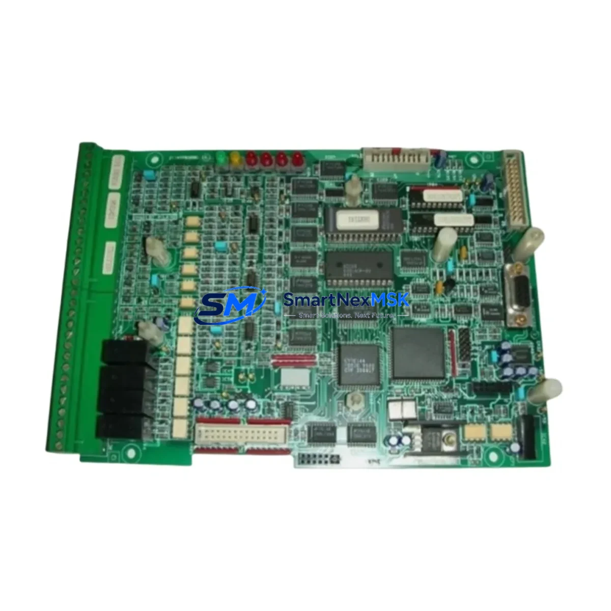
The AEREVB 211QS10540C is an original piezoelectric vibration sensor engineered for continuous-duty industrial automation environments. Designed as a direct maintenance spare within the 211QS series, this sensor supports rapid field replacement to minimize unplanned downtime on rotating machinery, conveyor drives, pump stations, and motor control systems. For maintenance engineers managing aging automation infrastructure, stocking the 211QS10540C as a certified spare ensures that vibration monitoring loops remain operational without extended lead times or compatibility risk.
Sourced directly from verified supply channels, each 211QS10540C unit undergoes pre-shipment functional testing to confirm output linearity, sensitivity calibration, and connector integrity before dispatch. With a 12-month warranty covering manufacturing defects and a documented compatibility profile across the 211QS platform, this sensor is a reliable choice for both planned maintenance schedules and emergency replacement scenarios.
Spare Maintenance Table
| Parameter | Specification |
|---|---|
| Part Number / SKU | 211QS10540C |
| Brand | AEREVB |
| Series | 211QS |
| Sensor Type | Piezoelectric Vibration Sensor |
| Output Signal | Analog (mV/g or 4–20 mA, series-dependent) |
| Measurement Range | Acceleration / Velocity (per 211QS series spec) |
| Mounting | Stud mount / magnetic base compatible |
| Connector Type | Industrial-grade shielded cable connector |
| Operating Temperature | -40°C to +120°C |
| IP Rating | IP67 (dust and water ingress protection) |
| Compatibility | 211QS series vibration monitoring systems |
| Application Environment | Motors, pumps, compressors, conveyor drives, rotating machinery |
| Origin | China (CN) |
| Pre-Shipment Testing | Functional output and sensitivity verification |
| Warranty | 12 Months — Manufacturing Defects Covered |
Maintenance Planning for Continuous Operation
When scheduling replacement of the 211QS10540C vibration sensor, maintenance engineers should treat the task as part of a broader control cabinet and instrumentation audit. Vibration sensors do not operate in isolation — their signal integrity depends on the health of the entire measurement chain. Before or during sensor replacement, the following components should be inspected and, where necessary, replaced as part of the same maintenance window:
Begin with the signal cable and shielded wiring harness connecting the sensor to the vibration monitoring module. Damaged insulation or broken shield continuity is a common source of noise that can mask genuine vibration anomalies. Next, verify the condition of the vibration monitoring input module or condition monitoring card in the control cabinet — a faulty input channel will render even a new sensor unreliable. If the system uses a signal isolator or signal conditioner between the sensor and the PLC/DCS analog input, inspect it for drift or output saturation.
Check the 24VDC or ±15VDC power supply module feeding the sensor excitation circuit. Voltage ripple or supply instability directly affects sensor output accuracy. For systems using terminal blocks and DIN rail wiring, inspect for loose connections, corrosion, or thermal cycling damage at the sensor input terminals. If the vibration signal feeds into a PLC analog input module (such as an SM331 or equivalent), verify the module’s input range configuration matches the sensor’s output type.
In systems where vibration data is used for predictive maintenance decisions, also review the HMI trend display configuration and alarm threshold settings to ensure they reflect the new sensor’s calibration baseline. For older installations, consider whether the backplane or rack connector seating the monitoring card shows signs of oxidation. Finally, if the system includes relay output modules for vibration trip signals, test the relay coil resistance and contact continuity as part of the same inspection cycle.
Stocking the 211QS10540C alongside compatible fuse holders and protection fuses for the sensor power circuit is recommended practice for facilities with critical rotating equipment. A single spare sensor without the supporting passive components can still result in extended downtime if a blown fuse or failed terminal block delays restoration.
Site Replacement Workflow
Replacing the 211QS10540C in the field follows a structured sequence to ensure system compatibility and minimize restoration time. Begin by isolating the sensor circuit at the control cabinet — de-energize the sensor power supply and confirm zero voltage at the sensor connector before disconnecting. Document the existing cable routing, connector orientation, and any cable tie positions to ensure the replacement is installed identically.
Remove the old 211QS10540C by unscrewing the stud mount or releasing the magnetic base, then disconnect the signal cable. Inspect the mounting surface for corrosion, thread damage, or contamination that could affect the new sensor’s coupling efficiency — poor mechanical coupling is a leading cause of inaccurate vibration readings after replacement. Clean the mounting surface and apply appropriate thread sealant if required by the installation standard.
Install the replacement 211QS10540C, torque the stud mount to the manufacturer’s specification, and reconnect the shielded signal cable. Re-energize the sensor power supply and verify the output signal at the monitoring module input — compare the baseline reading against historical trend data to confirm the new sensor is operating within the expected range. Update the maintenance log with the replacement date, sensor serial number, and post-installation baseline reading.
For facilities managing legacy automation systems where the original 211QS series documentation is no longer available, the 211QS10540C’s compatibility with standard industrial vibration monitoring interfaces allows it to serve as a reliable drop-in replacement without requiring control system reconfiguration. This makes it particularly valuable for extending the operational life of older motor control centers and distributed control system installations where sensor obsolescence would otherwise force a costly system upgrade.
Spare Parts Support FAQ
Q1: What is the shelf life of the 211QS10540C when stored as a spare?
Piezoelectric vibration sensors like the 211QS10540C have an extended shelf life when stored correctly. Keep the unit in its original packaging in a dry, temperature-controlled environment (10°C–30°C, relative humidity below 70%, non-condensing). Avoid storing near strong magnetic fields or vibration sources. Under these conditions, the sensor can be held as a spare for 3–5 years without performance degradation. The 12-month warranty period begins from the date of shipment, not from the date of installation.
Q2: How do I verify compatibility before installing the 211QS10540C in my system?
Compatibility verification should cover three areas: (1) mechanical — confirm the mounting thread size and cable connector type match your existing installation; (2) electrical — verify the sensor’s output signal type (voltage or current) matches the input specification of your monitoring module or PLC analog card; (3) sensitivity — confirm the sensor’s sensitivity rating (mV/g) is consistent with the alarm and trip thresholds configured in your monitoring system. If you are replacing a sensor from a different manufacturer, request the full datasheet and compare specifications before installation.
Q3: What pre-shipment testing is performed on the 211QS10540C?
Each 211QS10540C unit is functionally tested prior to dispatch. Testing covers output signal continuity, sensitivity verification against the rated specification, connector integrity, and insulation resistance of the cable assembly. Units that do not meet specification are quarantined and not shipped. A test record is available upon request for quality-critical applications. The 12-month warranty covers manufacturing defects identified after installation under normal operating conditions.
Q4: Can the 211QS10540C be used as a long-term supply solution for ongoing maintenance programs?
Yes. SMARTNEXMSK maintains stock of the 211QS10540C to support ongoing maintenance programs and blanket spare parts agreements. For facilities with multiple 211QS series installations, volume purchasing arrangements are available to reduce per-unit cost and ensure consistent supply. Lead times for standard orders are typically short, and expedited shipment is available for emergency replacement scenarios. Contact our technical sales team to discuss a tailored spare parts supply agreement for your site.
© 2026 SMARTNEXMSK. All rights reserved.
Original Source: https://smartnexmsk.com
Contact: sales@smartnexmsk.com | +86 18259474341