Alcatel-Lucent OS9600/OS9700-CMM Retrofit-Ready Chassis Management Module: Seamless Compatibility for Legacy OmniSwitch Control System Upgrades
The Alcatel-Lucent OS9600/OS9700-CMM is a Chassis Management Module engineered for mission-critical network and industrial control environments where system continuity, backward compatibility, and minimal downtime are non-negotiable. As legacy OmniSwitch OS9600 and OS9700 chassis reach end-of-support milestones, facilities managers and automation engineers increasingly rely on verified retrofit-ready replacements to extend operational life, protect existing wiring infrastructure, and defer full platform migrations. This CMM module is sourced, tested, and shipped to meet those exact demands.
Whether you are replacing a failed unit in an active production environment, upgrading a redundant chassis management path, or consolidating spare inventory for a multi-site rollout, the OS9600/OS9700-CMM delivers the interface compatibility, management plane continuity, and physical form factor required for a direct drop-in installation without chassis modification.
Upgrade Compatibility Table
| Parameter | Details |
|---|---|
| Compatible Chassis | OmniSwitch OS9600, OS9700 series |
| Module Type | Chassis Management Module (CMM) |
| Slot Installation | CMM slot A / CMM slot B (redundant pair supported) |
| Backplane Interface | OS9600/OS9700 proprietary backplane bus — direct fit, no adapter required |
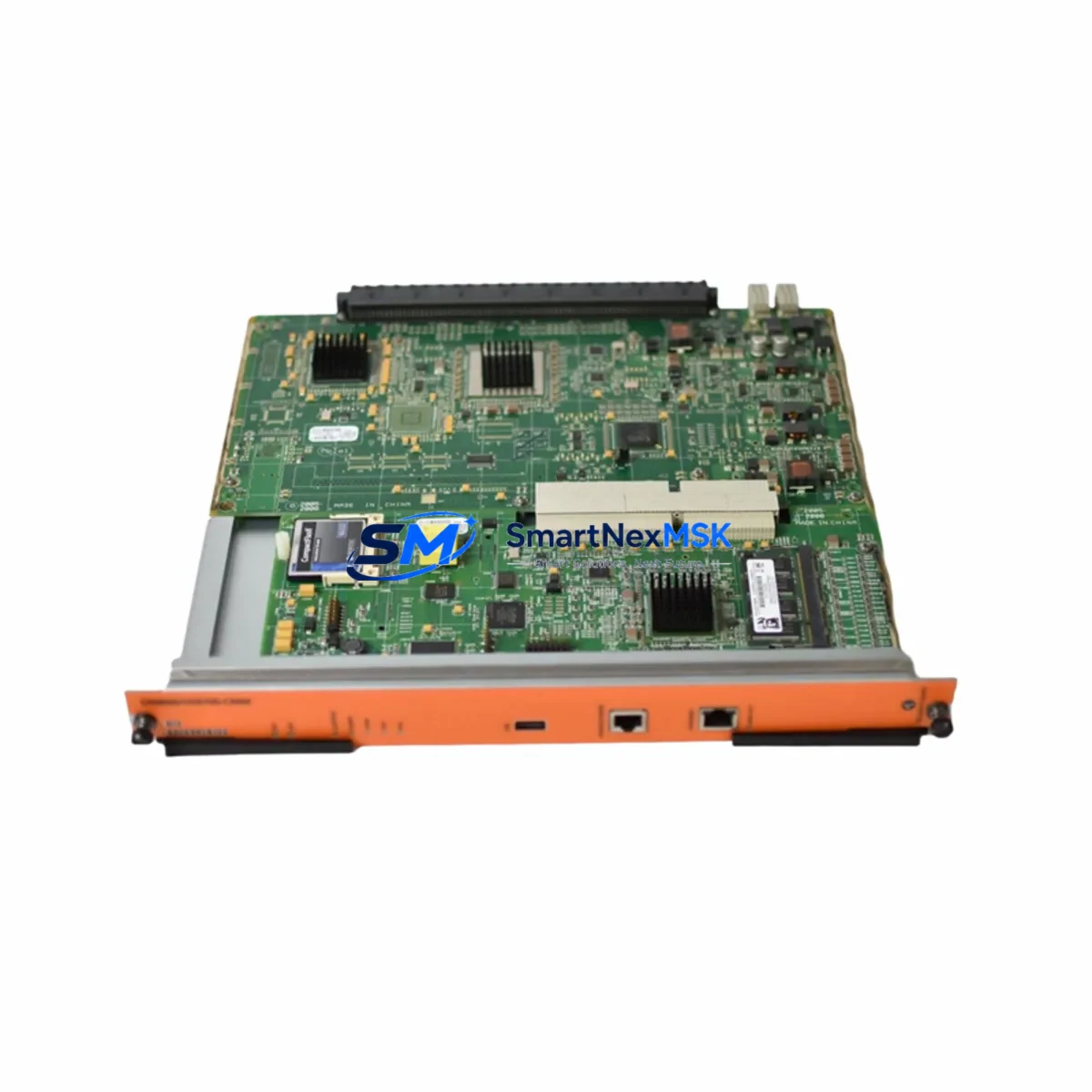
| Management Connectivity | Console port (RJ-45), Ethernet management port (10/100), USB for firmware/config |
| Communication Compatibility | AOS (Alcatel-Lucent OmniSwitch AOS) firmware compatible; supports SNMP v1/v2c/v3, Telnet, SSH, HTTPS |
| Redundancy Support | Hot-standby CMM failover supported when paired with second OS9600/OS9700-CMM |
| Replacement Recommendation | Direct replacement for end-of-life or failed OS9600-CMM / OS9700-CMM units |
| Commissioning Notes | Verify AOS firmware version before insertion; reload configuration from USB or TFTP server |
| Country of Origin | China (CN) |
| Warranty | 12-Month Warranty — covers hardware defects, DOA replacement, and functional verification |
Retrofit Planning for Existing Automation Systems
Replacing the OS9600/OS9700-CMM in a live or recently decommissioned chassis requires a structured approach. Before removing the existing module, engineers should document the current AOS configuration using the write memory command and back up the running configuration to a TFTP server or USB flash drive. This ensures that switch fabric parameters, VLAN assignments, spanning tree configurations, and QoS policies can be restored immediately after the new CMM initializes.
The OS9600 and OS9700 chassis typically house a combination of line cards and fabric modules alongside the CMM. Common co-installed components include OS9600-GNI-C24 Gigabit Ethernet line cards, OS9700-XNI-U2 10-Gigabit uplink modules, and OS9600-FAN fan tray assemblies. When planning a CMM retrofit, verify that the chassis power supply — typically an OS9600-PS-550W or OS9700-PS-900W — provides sufficient headroom for the replacement module’s initialization surge current. Undersized power supplies are a common cause of CMM boot failures during retrofit operations.
Terminal access during commissioning is established via the CMM’s RJ-45 console port using a standard rollover cable connected to a laptop or terminal server. Initial login uses the factory default credentials, after which the saved configuration is loaded. If the chassis previously operated with a redundant CMM pair, the second slot should be populated with a matching OS9600/OS9700-CMM unit to restore hot-standby failover capability. Mismatched firmware versions between primary and standby CMMs will prevent synchronization — always confirm that both modules run identical AOS release versions before enabling redundancy.
For sites migrating from older OS9000 series chassis to the OS9600/OS9700 platform, the transition typically involves remapping OS9000E-GNI-C24 port assignments to the new chassis slot numbering scheme. VLAN and link aggregation configurations are portable across AOS versions with minor syntax adjustments. Engineers should also verify that any connected OmniSwitch 6850 or OmniSwitch 6855 edge switches remain compatible with the management VLAN and spanning tree root assignments after the CMM swap.
In control cabinet environments where the OmniSwitch chassis serves as the backbone for SCADA or DCS communication, the CMM replacement must be coordinated with the control system team. Confirm that IP addresses assigned to the management port, in-band management VLANs, and SNMP community strings are preserved in the restored configuration. Any OmniVista 2500 NMS or third-party network management system polling the chassis should be temporarily suspended during the swap to avoid false-positive alarms and topology change notifications that could trigger upstream automation responses.
Downtime Control During System Migration
Minimizing downtime during a CMM replacement begins with pre-staging. Before the maintenance window opens, the replacement OS9600/OS9700-CMM should be bench-tested: power it in a spare chassis, confirm it boots to the AOS prompt, and pre-load the target firmware version via USB. This eliminates firmware update time from the critical path during the live swap.
In chassis configurations with redundant CMM slots, the migration can be executed with zero traffic interruption. The standby CMM is replaced first while the primary remains active. Once the new standby synchronizes and reaches hot-standby state — confirmed via the show cmm command — a controlled switchover transfers management plane control to the new module. The original primary is then replaced, completing the full CMM refresh without a single packet drop on the data plane.
For single-CMM chassis deployments, the maintenance window must account for the full boot cycle: typically 3–5 minutes from module insertion to full AOS initialization and configuration restore. Pre-positioning the configuration backup on USB and pre-staging the replacement module reduces this window to its minimum. Field engineers should have the console cable connected and terminal session open before the old module is extracted, enabling immediate visibility into the boot sequence and rapid intervention if the configuration restore requires manual correction.
All units shipped from our inventory undergo functional power-on testing and AOS boot verification prior to dispatch. Each OS9600/OS9700-CMM is covered by a 12-month warranty against hardware defects, with DOA replacement processed within 48 hours of confirmed fault report. Inventory is maintained in stock for same-week dispatch to minimize the gap between order placement and on-site availability.
Retrofit Support FAQ
Q1: Is this CMM a direct drop-in replacement for both the OS9600-CMM and OS9700-CMM?
Yes. The OS9600/OS9700-CMM module is physically and electrically compatible with both the OS9600 and OS9700 chassis CMM slots. No bracket modification, adapter, or chassis alteration is required. Confirm the AOS firmware version on the replacement module matches or is compatible with your chassis line card firmware before insertion.
Q2: What commissioning steps are required after installing the replacement CMM?
After physical installation, connect a console cable to the RJ-45 console port and monitor the boot sequence. Once AOS reaches the login prompt, restore the saved configuration from USB or TFTP. Verify management port IP assignment, VLAN configuration, and spanning tree parameters. If operating in redundant CMM mode, confirm hot-standby synchronization via show cmm before closing the maintenance window.
Q3: How do I verify wiring and terminal compatibility before the swap?
The OS9600/OS9700-CMM uses standard RJ-45 for console and management Ethernet — no proprietary cabling is required. Backplane connectivity is handled through the chassis slot interface; no field wiring is involved. Verify that the chassis backplane connector pins are clean and undamaged before inserting the replacement module. For management port connections, existing patch cables and switch port configurations require no modification.
Q4: What does the 12-month warranty cover, and how is a DOA claim processed?
The 12-month warranty covers all hardware defects and functional failures under normal operating conditions. If a unit arrives non-functional (DOA), contact our sales team within 7 days of receipt with the order number and a description of the fault. A replacement unit will be dispatched within 48 hours of fault confirmation. Warranty claims for field failures require the module serial number and a brief fault description submitted to sales@smartnexmsk.com.
© 2026 SMARTNEXMSK. All rights reserved.
Original Source: https://smartnexmsk.com
Contact: sales@smartnexmsk.com | +86 18259474341