ALLIED Vision C2514-M Maintenance-Ready Spare Stingray Automation
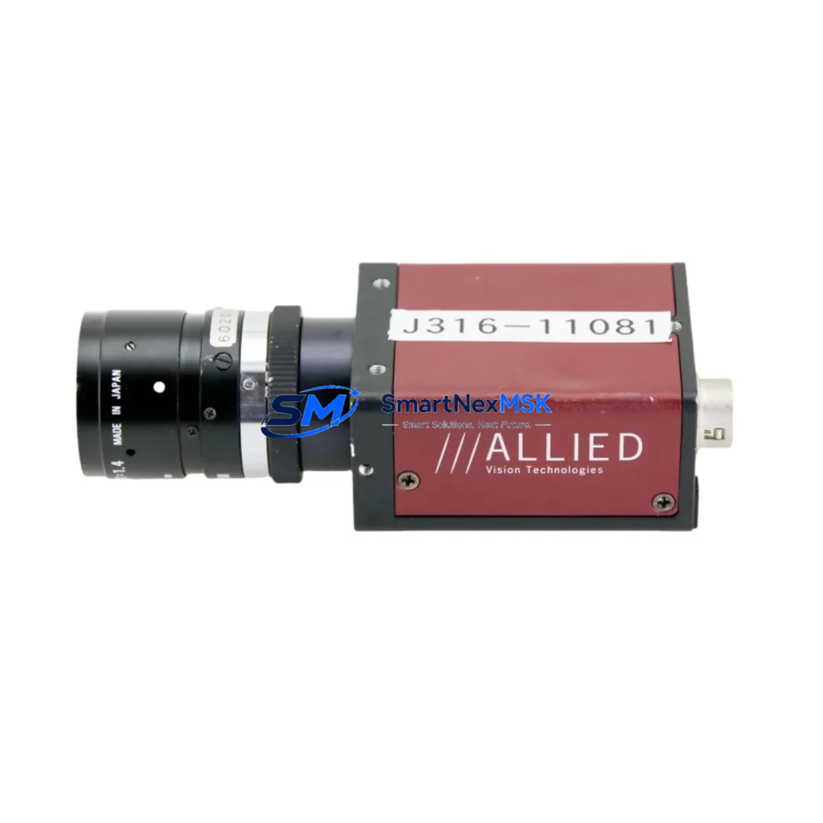
The ALLIED Vision C2514-M is a FireWire 800 (IEEE 1394b) monochrome CCD machine vision camera from the Stingray series, engineered for continuous-duty industrial imaging in automated inspection, quality control, and process monitoring applications. For maintenance engineers managing aging vision systems, securing a verified original spare — cross-referenced as F146B, 36-0442, 54-0442, 7520572050, and 0920-01014 LF-5SWC — is the single most effective measure to eliminate unplanned downtime caused by camera failure. This unit ships tested, with a 12-month warranty, and is ready for immediate site installation.
In high-throughput manufacturing environments, a failed vision camera can halt an entire production line. The C2514-M’s compact GigE-compatible form factor and standardized FireWire 800 interface make it a direct drop-in replacement for existing Stingray installations without requiring software reconfiguration, driver updates, or frame grabber changes — provided the host system retains its original IEEE 1394b controller card and cabling infrastructure.
Spare Maintenance Table
| Parameter | Specification |
|---|---|
| SKU / Part Numbers | C2514-M | F146B | 36-0442 | 54-0442 | 7520572050 | 0920-01014 | LF-5SWC |
| Brand / Series | ALLIED Vision / Stingray |
| Sensor Type | CCD Monochrome |
| Interface | FireWire 800 (IEEE 1394b) |
| Product Type | Machine Vision Camera |
| Origin | Germany (DE) |
| Compatibility | Stingray series; IEEE 1394b host controllers; standard C-mount lenses |
| Mounting | C-Mount lens interface; standard machine vision housing |
| Application Environment | Industrial inspection, automated quality control, process monitoring |
| Operating Conditions | Industrial-grade; suitable for controlled factory environments |
| Maintenance Recommendation | Inspect FireWire cable integrity, frame grabber card, and lens mount on each replacement cycle |
| Warranty | 12 Months — covers manufacturing defects; tested before shipment |
| Condition | Original spare; pre-shipment functional verification |
Maintenance Planning for Continuous Operation
When a Stingray C2514-M camera is flagged for replacement during a planned inspection or emergency shutdown, the replacement workflow should extend beyond the camera body itself. Maintenance engineers should treat the camera swap as an opportunity to audit the full imaging sub-system and adjacent control infrastructure.
Begin with the IEEE 1394b FireWire cable assembly — cable degradation is the leading cause of intermittent frame loss and false trigger events in Stingray installations. Replace any cable showing jacket cracking, bent connectors, or continuity irregularities. Next, verify the FireWire 800 host controller card (PCIe or PCI-X) seated in the vision PC: check for driver version compatibility with the current ALLIED Vision SDK and confirm IRQ allocation is not conflicting with other peripherals.
Inspect the C-mount lens and iris assembly for contamination, focus drift, or aperture sticking — lens degradation is frequently misdiagnosed as camera failure. If the system uses a motorized zoom or focus lens controller, verify its serial or analog control signal integrity from the vision controller output.
At the control cabinet level, check the 24 VDC power supply module feeding the vision PC and camera trigger circuit. Voltage ripple or transient spikes on the DC rail are a common root cause of camera resets and corrupted image frames. Inspect the DIN rail terminal blocks on the trigger input circuit for loose terminations, and verify the optocoupler isolation module on the trigger line is functioning within spec — degraded isolation can introduce noise that causes false triggers or missed acquisitions.
If the C2514-M is integrated into a PLC-controlled line, confirm the digital I/O module on the PLC rack that drives the camera trigger output is delivering clean, debounced signals within the camera’s trigger timing specification. For Siemens S7 or Allen-Bradley ControlLogix installations, also verify the communications module (PROFINET or EtherNet/IP) connecting the vision system to the PLC is not introducing latency that affects trigger synchronization.
Finally, if the system includes an HMI panel displaying live camera feeds or inspection results, confirm the HMI’s OPC-UA or Modbus TCP connection to the vision controller remains stable after the camera swap. A camera replacement that changes the device enumeration order on the FireWire bus can cause HMI display mapping to shift, requiring a brief reconfiguration of the vision software’s camera index assignment.
Site Replacement Workflow
Step 1 — Pre-Replacement Verification: Confirm the replacement unit’s SKU against the installed camera label (C2514-M, F146B, or cross-reference numbers 36-0442 / 54-0442). Photograph the existing cable routing, lens position, and mounting orientation before disassembly.
Step 2 — Safe Isolation: Power down the vision PC and isolate the 24 VDC trigger supply at the control cabinet. Do not hot-swap FireWire devices under load — this risks corrupting the host controller firmware.
Step 3 — Physical Swap: Remove the FireWire 800 cable, disconnect the lens, and unbolt the camera from its mounting bracket. Install the replacement C2514-M, re-mount the lens to the same focus position (use the reference photograph), and reconnect the FireWire cable. Torque the cable locking ring to finger-tight plus one quarter turn.
Step 4 — System Restart and Enumeration: Power up the vision PC. Confirm the camera is enumerated in the ALLIED Vision Vimba or AVT GigE SDK device manager. If the camera index has changed, update the vision application’s camera selection parameter.
Step 5 — Functional Verification: Run a live image capture at the production trigger rate. Verify frame rate, exposure, and gain settings match the pre-failure baseline. Confirm inspection pass/fail thresholds are producing expected results on known-good reference parts before returning the line to production.
This workflow minimizes mean time to recovery (MTTR) and ensures the replacement does not introduce new failure modes. Keeping one C2514-M spare on-site — alongside a spare FireWire cable and a tested lens — reduces camera-related downtime risk to near zero for Stingray-based vision systems.
Spare Parts Support FAQ
Q1: Is this C2514-M spare compatible with my existing Stingray vision system without software changes?
Yes. The C2514-M is a direct form-fit-function replacement for existing Stingray installations using IEEE 1394b FireWire 800 interfaces. No driver or SDK changes are required provided your host system is running a compatible ALLIED Vision SDK version. Confirm camera index assignment in your vision application after installation.
Q2: What is the recommended spare inventory strategy for Stingray cameras in a multi-line facility?
For facilities with three or more Stingray camera installations, we recommend maintaining one C2514-M spare per production zone. Camera MTBF in industrial environments typically ranges from 3–7 years depending on duty cycle and environmental conditions. A proactive spare inventory eliminates the 2–6 week lead time risk associated with sourcing cameras reactively after failure.
Q3: How is the unit tested before shipment?
Each C2514-M spare undergoes functional verification prior to dispatch: FireWire interface enumeration, live image capture at rated frame rate, and visual inspection of the lens mount and connector housing. Units that do not pass functional verification are not shipped. A 12-month warranty covers manufacturing defects from the date of receipt.
Q4: Can this unit replace cross-reference part numbers F146B, 36-0442, 54-0442, 7520572050, or 0920-01014 LF-5SWC?
Yes. These part numbers are cross-references for the same ALLIED Vision Stingray C2514-M camera unit used across different procurement systems, OEM integrations, and regional distributor catalogs. All cross-reference numbers refer to the same physical unit and are interchangeable for maintenance replacement purposes.
© 2026 SMARTNEXMSK. All rights reserved.
Original Source: https://smartnexmsk.com
Contact: sales@smartnexmsk.com | +86 18259474341