Alston CBK 132.1 029.210 753 Spare for Modnet 1/D Automation: Spare Parts Replacement & Industrial Downtime Risk Control
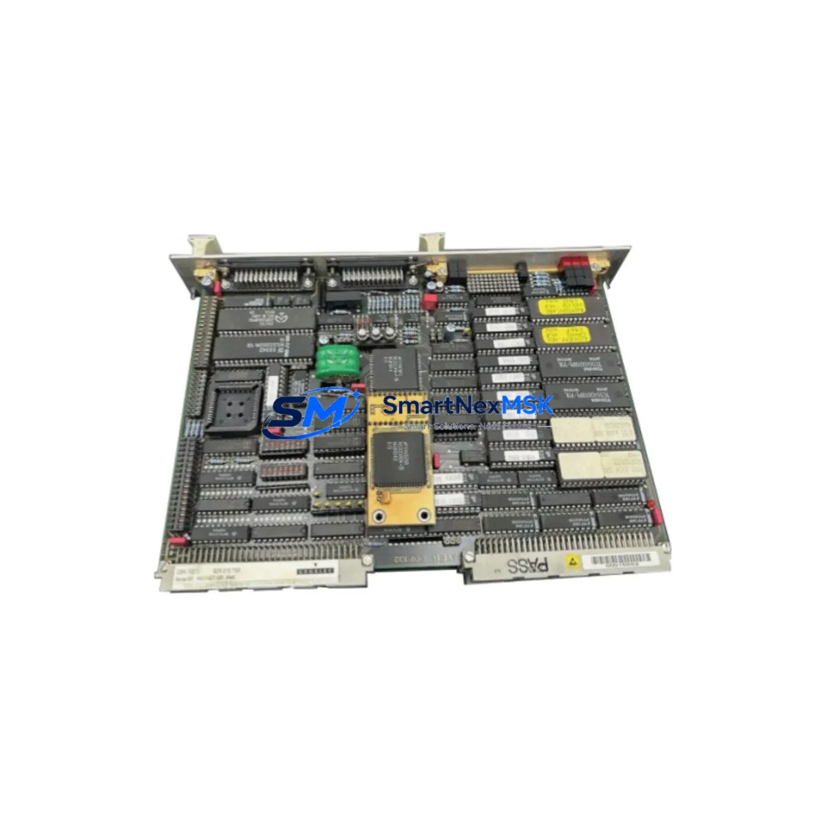
The Alston CBK 132.1 029.210 753 is an original Modnet 1/D Serial I/O Communication Module designed for industrial automation control systems. As a maintenance-ready spare, this module supports rapid field replacement in legacy and active Modnet 1/D architectures, enabling maintenance engineers to restore serial communication links and resume production with minimal downtime. Whether you are managing a planned overhaul, responding to an unscheduled fault, or building a strategic spare parts inventory, the CBK 132.1 029.210 753 is a verified, test-shipped component backed by a 12-month warranty.
Industrial facilities operating Alston CBK Modnet 1/D systems depend on reliable serial I/O communication between PLCs, DCS controllers, and field devices. A failed or degraded communication module can cascade into full line shutdowns. Stocking the 132.1 029.210 753 as a cold standby spare is a proven strategy for reducing mean time to repair (MTTR) and protecting production continuity in process-critical environments.
Spare Maintenance Table
| Parameter | Specification / Detail |
|---|---|
| Part Number / SKU | 132.1 029.210 753 |
| Brand | Alston CBK |
| Series | Modnet 1/D |
| Module Type | Serial I/O Communication Module |
| Origin | Germany (DE) |
| Communication Interface | Serial (RS-232 / RS-485, Modnet protocol) |
| Compatibility | Alston CBK Modnet 1/D control systems; legacy serial I/O backplane architectures |
| Installation | DIN-rail or backplane slot mount; refer to Modnet 1/D system documentation for slot assignment |
| Operating Environment | Industrial control cabinet; standard IEC 61131 environmental conditions |
| Weight | 1,000 g (approx.) |
| Maintenance Recommendation | Inspect connector pins and serial port integrity during scheduled cabinet inspections; replace if communication errors or CRC faults are logged |
| Warranty | 12 Months — all units tested before shipment |
| Supply Availability | Long-term spare parts support; suitable for legacy system life extension |
Maintenance Planning for Continuous Operation
When replacing the Alston CBK 132.1 029.210 753 Serial I/O Communication Module, a thorough maintenance engineer will not limit the inspection to the module itself. The Modnet 1/D communication architecture relies on a tightly integrated set of components, and a fault in the serial I/O layer often signals stress or degradation in adjacent parts of the control cabinet.
Begin by verifying the 24 VDC power supply module feeding the Modnet 1/D backplane — voltage sag or ripple is a common root cause of serial communication instability. Inspect the backplane bus connector and slot contacts for oxidation or mechanical wear, as poor backplane contact can mimic a module failure. Check the system CPU or master communication module for firmware version compatibility with the replacement 132.1 029.210 753 unit, particularly in older Modnet 1/D installations where firmware revisions may affect serial handshake behavior.
Review the terminal blocks and field wiring connected to the serial I/O ports — loose or corroded terminals are a frequent source of intermittent communication faults that are misdiagnosed as module failures. If the system uses signal isolators between the Modnet 1/D module and field devices, verify that the isolators are within their rated operating range and have not drifted. Inspect any surge protection devices on the serial lines, as these are sacrificial components that may have absorbed transient energy during a fault event.
For systems with relay output modules or digital I/O expansion modules in the same cabinet, confirm that coil suppression diodes are intact and that no inductive kickback is reaching the communication bus. If the Modnet 1/D system interfaces with an HMI panel via serial link, test the HMI communication parameters (baud rate, parity, stop bits) after module replacement to confirm the link is re-established correctly. Where RS-485 network segments are used, verify termination resistors at both ends of the bus and check for correct bus biasing.
Procurement engineers building a spare parts kit for Modnet 1/D systems should consider stocking the power supply module, a spare CPU/master module, at least one digital I/O module, a set of terminal block connectors, and a signal isolator alongside the 132.1 029.210 753 to cover the most common failure modes in a single cabinet inspection cycle.
Site Replacement Workflow
Step 1 — Fault Isolation: Use the Modnet 1/D diagnostic software or the system HMI to confirm that the fault is isolated to the 132.1 029.210 753 module. Log the error codes and communication fault flags before powering down.
Step 2 — Safe Isolation: Follow your site LOTO (Lockout/Tagout) procedure. Isolate the control cabinet supply and discharge any residual energy in the backplane before removing the module.
Step 3 — Module Removal: Release the module locking mechanism and carefully extract the 132.1 029.210 753 from its backplane slot. Note the slot address for correct reinstallation of the replacement unit.
Step 4 — Compatibility Verification: Confirm that the replacement module’s hardware revision and firmware version are compatible with your Modnet 1/D system version. Cross-reference the part number 132.1 029.210 753 against your system’s spare parts list or OEM documentation.
Step 5 — Installation & Commissioning: Insert the replacement module into the correct backplane slot. Restore power and observe the system startup sequence. Verify that the serial I/O communication link is re-established and that no fault flags remain active on the HMI or diagnostic terminal.
Step 6 — Functional Test: Run a communication loop test between the Modnet 1/D module and connected field devices. Confirm data integrity, correct I/O mapping, and absence of CRC errors before returning the system to production.
This workflow is designed to minimize downtime and ensure that the replacement module is fully validated before the system resumes normal operation. All units supplied by SMARTNEXMSK are tested before shipment to reduce the risk of DOA (dead-on-arrival) failures in the field.
Spare Parts Support FAQ
Q1: Is the Alston CBK 132.1 029.210 753 a direct drop-in replacement for the original module?
A: Yes. The 132.1 029.210 753 is an original Alston CBK Modnet 1/D Serial I/O Communication Module. It is designed as a direct slot-compatible replacement for the same part number in Modnet 1/D systems. We recommend verifying the hardware revision against your system documentation before installation, particularly for older installations where multiple hardware revisions may exist.
Q2: How is the module tested before shipment?
A: Every unit undergoes functional testing prior to dispatch. Testing includes power-on verification, serial port communication checks, and visual inspection of connector integrity. A test report is available upon request for critical spare applications.
Q3: What is the warranty coverage and what does it include?
A: All units are covered by a 12-month warranty from the date of shipment. The warranty covers manufacturing defects and functional failures under normal operating conditions. It does not cover damage caused by incorrect installation, overvoltage, or environmental conditions outside the module’s rated specifications.
Q4: Can you support long-term or repeat supply of this spare part?
A: Yes. SMARTNEXMSK maintains long-term sourcing capability for Alston CBK Modnet 1/D components, including the 132.1 029.210 753. We support both single-unit emergency orders and bulk procurement for planned maintenance programs. Contact our team to discuss inventory reservation or scheduled supply agreements.
© 2026 SMARTNEXMSK. All rights reserved.
Original Source: https://smartnexmsk.com
Contact: sales@smartnexmsk.com | +86 18259474341