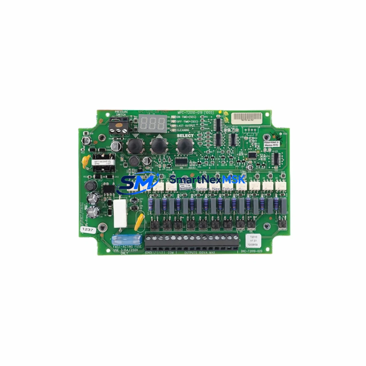
AMETEK DNC-T2010-R20 Maintenance-Ready Spare for DNC Automation
The AMETEK DNC-T2010-R20 is a relay output module designed for the AMETEK DNC Series programmable logic control platform, widely deployed in industrial process automation, power generation auxiliary systems, and precision measurement-driven control applications. As a maintenance-ready original spare, the DNC-T2010-R20 is stocked, pre-tested, and ready for immediate dispatch to support planned shutdowns, emergency replacements, and long-term spare parts inventory programs.
For maintenance engineers managing aging DNC-based control cabinets, sourcing a verified original relay output module is critical. Counterfeit or incompatible substitutes risk relay chatter, false output signals, and cascading faults across downstream actuators and field devices. The DNC-T2010-R20 is supplied as an original AMETEK component, fully compatible with the DNC backplane architecture, and backed by a 12-month warranty covering manufacturing defects and functional failure under normal operating conditions.
Spare Maintenance Table
| Parameter | Specification / Details |
|---|---|
| Part Number / SKU | DNC-T2010-R20 |
| Brand | AMETEK |
| Series | DNC Series |
| Module Type | Relay Output Module |
| Output Type | Relay (dry contact) |
| Compatible Platform | AMETEK DNC Series PLC / Control System |
| Backplane Compatibility | DNC Series standard backplane |
| Operating Voltage | Per DNC Series specification (24VDC logic bus typical) |
| Contact Rating | Per relay output specification (typically 2A / 250VAC per channel) |
| Operating Temperature | 0°C to +60°C (industrial panel environment) |
| Mounting | DNC backplane slot insertion |
| Application Environment | Industrial control cabinet, process automation, power auxiliary |
| Condition | Original, new or refurbished-to-spec, pre-shipment tested |
| Warranty | 12 Months — manufacturing defect & functional failure coverage |
| Lead Time | In stock — same-day or next-business-day dispatch available |
| Origin | USA (AMETEK Inc.) |
Maintenance Planning for Continuous Operation
When a relay output module such as the DNC-T2010-R20 is flagged during routine inspection or fails in service, experienced maintenance engineers know that the fault rarely exists in isolation. A systematic cabinet inspection should accompany any relay output module replacement to prevent repeat failures and unplanned downtime.
Begin by verifying the DNC Series power supply module — relay coil energization depends on a stable 24VDC logic bus, and a degraded power supply can cause intermittent relay dropout that mimics module failure. Inspect the DNC backplane for oxidized connector pins or mechanical damage at the slot where the DNC-T2010-R20 is seated; a poor backplane contact is a common root cause of relay output anomalies.
Check the DNC digital input module paired with this output module in the same control loop — if the input module is misreading field signals, the relay output will cycle incorrectly regardless of module condition. Review the DNC CPU or processor module event log for output scan errors or watchdog faults that may have contributed to the relay module failure.
On the field wiring side, inspect the terminal blocks and wiring harness connected to the relay output channels. Loose terminations, corroded lugs, or undersized conductors can cause arcing at relay contacts, accelerating contact wear and shortening module life. If the relay outputs drive inductive loads such as solenoid valves or motor contactors, verify that surge suppression diodes or RC snubbers are installed across the load — their absence is a leading cause of premature relay contact failure.
For systems where the DNC-T2010-R20 interfaces with downstream intermediate relay modules or solid-state relay (SSR) banks, confirm that coil voltage ratings and contact current ratings remain within specification after any field wiring changes. Where the control cabinet includes a DNC communications module for MODBUS, PROFIBUS, or proprietary AMETEK network protocols, verify that the module’s I/O mapping table still correctly references the relay output addresses after the replacement module is installed.
If the system includes a DNC analog output module in the same cabinet driving proportional control valves or variable speed drives, cross-check that the analog outputs remain stable during the relay output module swap — backplane power fluctuations during hot-swap or power cycling can temporarily affect analog output accuracy. Finally, review the HMI or operator panel alarm history for any latched relay fault alarms that must be cleared after the replacement is confirmed functional.
Maintaining a minimum of one DNC-T2010-R20 in your on-site spare parts inventory, alongside a spare DNC power supply module and a spare DNC CPU module, is the recommended baseline for facilities operating DNC-based control systems in critical process environments.
Site Replacement Workflow
Step 1 — Isolation & Safety: Follow your site LOTO (Lockout/Tagout) procedure. De-energize the DNC control cabinet and confirm zero-energy state before opening the enclosure. Document the current relay output status from the HMI or SCADA historian before shutdown.
Step 2 — Module Identification: Confirm the slot address of the DNC-T2010-R20 in the backplane. Cross-reference the DNC system configuration file or I/O map to verify the module address, relay channel assignments, and any forced output states that may be active in the CPU.
Step 3 — Physical Removal: Release the module locking mechanism and extract the DNC-T2010-R20 from the backplane slot. Inspect the backplane connector for debris or pin damage before inserting the replacement unit.
Step 4 — Replacement Installation: Insert the new DNC-T2010-R20 into the correct backplane slot. Ensure full seating and engage the locking mechanism. Reconnect field wiring terminal blocks, verifying correct channel-to-terminal mapping against the as-built wiring diagram.
Step 5 — Power-Up & Verification: Restore cabinet power in sequence per the DNC system startup procedure. Confirm the CPU recognizes the replacement module without I/O configuration faults. Perform a relay output functional test — command each relay channel ON and OFF from the HMI or engineering workstation and verify field device response.
Step 6 — Documentation: Record the replacement in the equipment maintenance log, including the old module serial number, new module serial number, date, technician name, and post-replacement test results. Update the spare parts inventory to trigger reorder of a replacement DNC-T2010-R20 for the on-site stock.
This workflow minimizes mean time to repair (MTTR) and ensures system compatibility is maintained without requiring DNC CPU reprogramming or I/O reconfiguration in standard replacement scenarios.
Spare Parts Support FAQ
Q1: Is the DNC-T2010-R20 supplied as a new original or refurbished unit?
We supply the DNC-T2010-R20 as original AMETEK stock — either new-in-box or professionally refurbished to original specification, depending on availability. All units undergo pre-shipment functional testing. The 12-month warranty applies equally to both supply conditions and covers manufacturing defects and functional failure under normal operating conditions.
Q2: How do I confirm compatibility before ordering?
Compatibility is confirmed by matching the full part number DNC-T2010-R20 against your DNC system I/O configuration file or the module label on the installed unit. If your system uses a variant designation or a superseded part number, contact our technical team with your DNC CPU model and backplane configuration — we will verify cross-compatibility before shipment.
Q3: What is the recommended spare parts inventory strategy for DNC relay output modules?
For facilities with a single DNC system, maintain a minimum of one DNC-T2010-R20 on-site. For multi-system or critical-process facilities, a 10–15% spare ratio relative to installed relay output module count is recommended. Modules stored in a climate-controlled environment with original packaging retain full specification for 5+ years.
Q4: What pre-shipment testing is performed on each DNC-T2010-R20?
Each unit is tested for relay coil continuity, contact resistance, output channel isolation, and backplane connector integrity prior to dispatch. A test report is available upon request. Units are packed in anti-static packaging with physical protection for international freight.
© 2026 SMARTNEXMSK. All rights reserved.
Original Source: https://smartnexmsk.com
Contact: sales@smartnexmsk.com | +86 18259474341