AMK KW40 Retrofit-Ready Servo Axis for AMKASYN KW Systems: Compatible Modernization & Smooth Legacy Upgrade
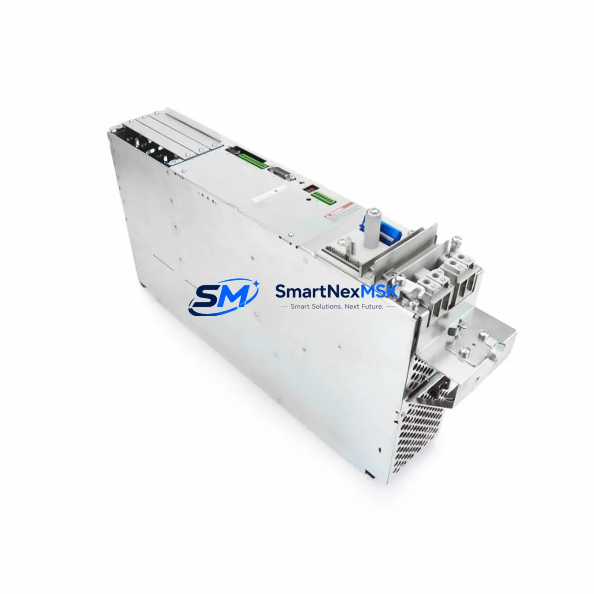
The AMK KW40 is a 40 A servo drive axis module engineered for the AMKASYN KW series multi-axis servo system. Designed for direct rack-mount installation in AMK AMKASYN control cabinets, the KW40 delivers high-dynamic torque control, synchronous axis coordination, and deterministic fieldbus communication — making it the preferred choice for engineers tasked with replacing discontinued axis modules, modernizing aging servo lines, or recovering production capacity after an unplanned drive failure.
Whether you are migrating from an earlier AMK KW20 or KW15 axis module, expanding an existing multi-axis rack with additional servo channels, or rebuilding a complete AMKASYN drive cabinet from scratch, the KW40 slots directly into the standard AMK backplane without mechanical modification. Its firmware is compatible with the AMK AIPEX Pro engineering environment, preserving existing motion programs, cam profiles, and electronic gearing ratios already commissioned on the machine.
Upgrade Compatibility Table
| Parameter | AMK KW40 (This Unit) | Retrofit Notes |
|---|---|---|
| Continuous Output Current | 40 A | Verify motor nameplate; replaces KW20/KW15 with higher headroom |
| Backplane Interface | AMK AMKASYN KW standard slot | Direct plug-in; no adapter required for KW-series racks |
| DC Bus Connection | Shared DC bus via AMK KE/KD supply module | Confirm KE/KD supply capacity covers total axis load after upgrade |
| Communication Protocol | AMK SERCOS II / proprietary AMK fieldbus | Compatible with existing SERCOS ring; no ring reconfiguration needed |
| Engineering Software | AMK AIPEX Pro | Existing axis parameters and cam tables transferable without rewrite |
| Motor Feedback | Resolver / EnDat 2.1 encoder | Confirm feedback cable pinout matches motor; adapter cables available |
| Installation Format | Rack-mount, DIN rail compatible | Same mechanical footprint as KW20/KW15; no cabinet rework required |
| Commissioning Tool | AIPEX Pro via RS-232 / USB programming cable | Use AMK programming cable; verify COM port driver before site visit |
| Warranty | 12-Month Warranty — covers functional defects under normal operating conditions | |
Retrofit Planning for Existing Automation Systems
A successful KW40 retrofit begins well before the module arrives on site. Start by auditing the existing control cabinet: document the current AMK KE supply module rating and confirm that its DC bus capacity can support the KW40’s 40 A continuous draw alongside all other axis modules already installed. In multi-axis racks where a KW20 or KW15 is being replaced, the increased current headroom of the KW40 is typically welcome — but the supply module must be sized accordingly.
Next, photograph and record every terminal connection on the outgoing axis module. The KW40 uses the same backplane connector as the AMKASYN KW family, but motor power terminals, brake control wiring, and feedback cable routing should be verified against the machine’s original wiring diagram. If the machine uses an AMK KD regenerative supply module for energy recovery, confirm that the regenerative braking parameters in AIPEX Pro are re-entered correctly after module swap — these are axis-specific and are not automatically inherited from the rack configuration.
For machines running a SERCOS II communication ring, the KW40 integrates seamlessly. The SERCOS ring address is set via rotary switch on the module face; simply assign the same address as the outgoing module and the AMK iSA controller or host PLC will recognize the axis without topology changes. If the host controller is a third-party system — such as a Siemens S7-300 or Beckhoff CX series — communicating via a SERCOS master card, no changes to the master configuration are required provided the axis address is preserved.
I/O wiring deserves careful attention. Digital inputs for axis enable, drive ready, and fault reset are routed through the backplane in AMKASYN systems, but some machine builders add external terminal blocks for local override or safety relay integration. Verify that any AMK I/O expansion modules mounted in the same rack are not affected by the slot position change. If the machine uses an AMK BUS module for distributed I/O, confirm that the bus address table in the controller program still maps correctly after the axis module is replaced.
HMI screens that display axis status, position feedback, or fault codes typically read data from the controller’s memory map rather than directly from the drive. After the KW40 is installed and commissioned, cycle through all relevant HMI pages on the AMK operator panel or third-party HMI to confirm that position values, speed readouts, and alarm displays are updating correctly. Pay particular attention to any custom HMI screens that reference axis-specific parameter numbers, as these may need to be re-validated if the firmware version of the KW40 differs from the outgoing module.
Finally, before returning the machine to production, run a full motion test sequence: jog each axis through its travel range, execute a homing cycle, and run the machine’s standard production program at reduced speed. Verify that electronic gearing ratios between the KW40 and adjacent axes — such as a KW25 or KW30 on the same rack — are performing as expected. Log the commissioning results and retain them alongside the 12-month warranty documentation supplied with the module.
Downtime Control During System Migration
Minimizing production downtime during an AMKASYN KW40 swap requires preparation, not speed. The most effective approach is to pre-configure the replacement module off-line using AIPEX Pro before the maintenance window begins. Export the full axis parameter set from the outgoing module while the machine is still running — AIPEX Pro allows parameter upload via the programming cable without interrupting machine operation in most firmware versions. Save the parameter file, the cam table, and the SERCOS ring configuration to a secure backup location.
During the maintenance window, power down the cabinet following the correct AMK shutdown sequence: disable all axes, stop the SERCOS ring, then remove DC bus power before disconnecting the module. The KW40 can be physically installed in under ten minutes in a well-organized cabinet. Reconnect motor power, feedback, and brake wiring, then restore DC bus power and re-initialize the SERCOS ring. Download the pre-saved parameter file to the KW40 via AIPEX Pro, verify axis address assignment, and perform a short jog test before releasing the machine to production.
For critical production lines where even a brief unplanned stop is unacceptable, consider keeping a pre-configured AMK KW40 spare module on the shelf with parameters already loaded. This reduces the swap-and-commission cycle to under 30 minutes, protecting both production schedules and the integrity of the original control logic. All modules supplied by SMARTNEXMSK are pre-tested under load before shipment and include a 12-month warranty, giving your maintenance team confidence that the replacement unit will perform from the first power-on.
Retrofit Support FAQ
Q1: Is the AMK KW40 a direct drop-in replacement for the KW20 or KW15 in the same rack?
Yes. The KW40 uses the same AMKASYN KW backplane slot and connector as the KW20 and KW15. No mechanical modification to the rack or cabinet is required. You will need to verify that the DC bus supply module (KE or KD) has sufficient capacity for the higher continuous current rating of the KW40, and re-enter axis parameters via AIPEX Pro after installation.
Q2: Can I transfer my existing axis parameters and cam profiles to the KW40 without rewriting the program?
In most cases, yes. AIPEX Pro supports parameter upload from the outgoing module and download to the KW40. Cam tables, electronic gearing ratios, and homing parameters are preserved in the parameter file. Minor adjustments to current limits or encoder feedback settings may be required if the KW40 firmware version differs from the original module. Always perform a reduced-speed test run after parameter transfer before returning to full production speed.
Q3: What wiring checks are required before powering up the KW40?
Verify motor power phase sequence (U, V, W), brake control polarity, and feedback cable pinout (resolver or EnDat). Confirm that the SERCOS ring fiber connections are seated correctly and that the axis address rotary switch matches the address of the outgoing module. Check that all terminal screws are torqued to specification and that no wiring was disturbed in adjacent modules during the swap.
Q4: What does the 12-month warranty cover, and how is it handled?
All AMK KW40 modules supplied by SMARTNEXMSK carry a 12-month warranty covering functional defects under normal operating conditions. Each unit is tested under load prior to shipment. If a warranty claim arises, contact sales@smartnexmsk.com with the module serial number and a description of the fault. Replacement or repair is coordinated promptly to minimize your downtime exposure.
© 2026 SMARTNEXMSK. All rights reserved.
Original Source: https://smartnexmsk.com
Contact: sales@smartnexmsk.com | +86 18259474341
