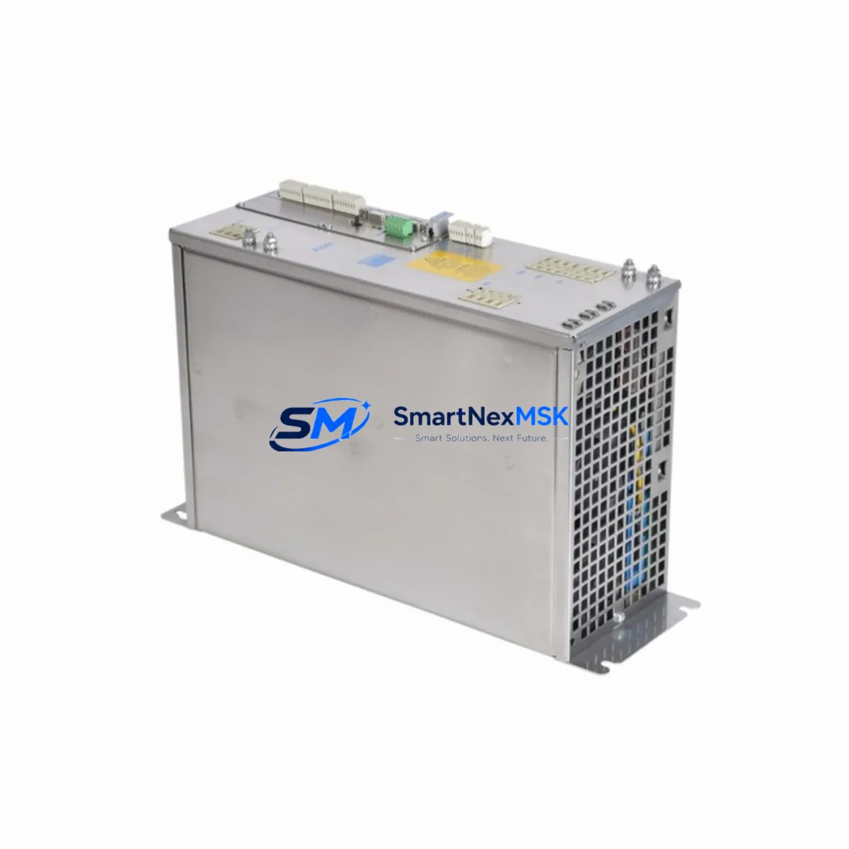
AMPLIFIER PRD-0051AMPC-X0 Retrofit-Ready Servo Drive for PRD Series Control Systems
The AMPLIFIER PRD-0051AMPC-X0 is a high-performance servo drive engineered for seamless integration into PRD Series automation platforms. Designed with retrofit compatibility at its core, this unit serves as a direct replacement for aging or discontinued axis controllers in legacy motion control cabinets. Whether you are upgrading a multi-axis servo system, recovering from an unplanned drive failure, or executing a planned modernization of your production line, the PRD-0051AMPC-X0 delivers the electrical and mechanical compatibility required to minimize engineering rework and reduce total downtime.
Industrial facilities operating PRD Series control architectures frequently encounter obsolescence challenges as original equipment manufacturers phase out legacy servo components. The PRD-0051AMPC-X0 addresses this directly by maintaining backward-compatible terminal wiring, matching the original backplane connector footprint, and supporting the axis addressing schemes used in existing PLC programs. Engineers responsible for maintaining servo-driven conveyors, CNC axes, robotic joints, or precision positioning stages will find this unit a reliable drop-in solution that eliminates the need for full system redesign.
Each unit is pre-tested prior to shipment, covering power-on initialization, encoder feedback verification, and basic motion command response. A 12-month warranty is included with every order, covering manufacturing defects and component failures under normal operating conditions.
Upgrade Compatibility Table
| Parameter | PRD-0051AMPC-X0 Specification | Retrofit Notes |
|---|---|---|
| Series Compatibility | PRD Series | Direct replacement for PRD axis drive slots |
| Connector / Backplane Interface | PRD-standard backplane pinout | No adapter required for same-series racks |
| Terminal Wiring | Compatible with original PRD wiring harness | Verify U/V/W motor phase sequence before power-on |
| Communication Protocol | Matches PRD Series controller bus | Confirm axis node address in PLC program |
| Encoder Feedback | Incremental / absolute encoder input | Retain original encoder cable; verify resolution setting |
| Power Supply Requirement | Per PRD Series DC bus specification | Confirm bus capacitor bank capacity before hot-swap |
| Module Address | Configurable via DIP switch or software | Match original axis address to avoid program remapping |
| HMI Screen Compatibility | No HMI screen changes required | Axis tag names remain valid if address is preserved |
| Warranty | 12 Months | Covers manufacturing defects under normal operation |
Retrofit Planning for Existing Automation Systems
A successful retrofit of the PRD-0051AMPC-X0 into an existing control cabinet begins with a thorough audit of the surrounding system components. In most PRD Series installations, the servo drive shares a rack with the main CPU module, I/O expansion modules, and a dedicated power supply module. Before removing the failed or obsolete drive, engineers should document the current axis address, encoder parameter settings, and any drive-specific gain tuning values stored in the controller program.
The PRD Series rack and backplane system is designed for modular replacement, meaning the PRD-0051AMPC-X0 can be inserted into the original slot without disturbing adjacent modules. However, it is advisable to power down the entire control cabinet and discharge the DC bus capacitors before performing the swap. The power supply module feeding the servo bus should be verified to have sufficient current headroom for the replacement drive, particularly in multi-axis configurations where bus loading is shared across several axis drives.
Terminal block wiring for the motor phases (U, V, W) and the brake control circuit should be transferred directly from the original drive. If the installation uses a separate regenerative braking resistor or a shared DC bus with other drives, the wiring topology must be preserved exactly. The encoder cable connecting the servo motor to the drive feedback input should be inspected for continuity and shielding integrity before reconnection.
For systems using a communication module or fieldbus adapter — such as a PROFIBUS DP interface card, DeviceNet scanner, or EtherNet/IP adapter — the axis node address configured on the PRD-0051AMPC-X0 must match the address previously assigned to the failed drive. Failure to match the node address will cause the PLC program to report a communication fault and prevent the axis from being enabled. In installations where the HMI panel displays axis status using tag-based addressing, preserving the original axis address eliminates the need to modify HMI screen logic or tag databases.
Programming cables used during commissioning — such as a USB-to-serial programming cable compatible with the PRD Series configuration software — should be prepared in advance. After physical installation, the drive parameters including current limits, velocity loop gains, position loop gains, and encoder resolution must be verified against the original commissioning sheet. If the original parameter file is available, it can be downloaded directly to the replacement drive to restore factory-tuned performance without manual re-entry.
Downtime Control During System Migration
Minimizing production downtime during a servo drive replacement requires advance preparation and a structured commissioning sequence. The recommended approach is to stage the PRD-0051AMPC-X0 as a pre-configured spare, with all axis parameters loaded and verified offline before the maintenance window begins. This reduces the on-site installation time to the physical swap, wiring reconnection, and a brief motion test sequence.
Where production schedules permit only a narrow maintenance window, the following sequence is recommended: isolate the affected axis from the motion program using the controller’s axis inhibit function, perform the physical drive replacement, restore axis parameters from the saved configuration file, re-enable the axis in the PLC program, and execute a slow-speed jog test before returning the machine to automatic cycle. This approach preserves the original program logic without modification and avoids the risk of unintended motion during the commissioning phase.
For multi-axis systems where the failed drive shares a DC bus with other active axes, it is critical to verify that the bus voltage recovers correctly after the replacement drive is powered on. A bus voltage measurement at the drive terminals, compared against the specification for the PRD Series power supply module, confirms that the system is ready for full-speed operation. The 12-month warranty on the PRD-0051AMPC-X0 provides additional assurance that any latent manufacturing defects will be addressed without additional cost during the initial post-installation period.
Retrofit Support FAQ
Q: Is the PRD-0051AMPC-X0 a direct drop-in replacement for the original PRD Series axis drive?
A: Yes. The PRD-0051AMPC-X0 is designed to match the original backplane connector, terminal wiring layout, and axis addressing scheme of the PRD Series. In most installations, no mechanical modification or wiring change is required beyond restoring the original parameter configuration.
Q: What commissioning steps are required after installing the replacement drive?
A: After physical installation, verify the axis node address, download the saved parameter file, confirm encoder feedback signal integrity, and perform a slow-speed jog test before returning the axis to automatic operation. A programming cable compatible with the PRD Series configuration software is required for parameter download.
Q: How do I confirm wiring compatibility before powering on the replacement drive?
A: Compare the terminal block layout of the PRD-0051AMPC-X0 against the original wiring diagram. Verify motor phase sequence (U/V/W), encoder cable pinout, brake control wiring, and DC bus connections. Measure insulation resistance on the motor cable before reconnecting to the drive output terminals.
Q: What does the 12-month warranty cover?
A: The 12-month warranty covers manufacturing defects and component failures under normal operating conditions. It does not cover damage resulting from incorrect installation, overvoltage events, or operation outside the specified environmental ratings. Warranty claims are processed through sales@smartnexmsk.com with proof of purchase and a fault description.
© 2026 SMARTNEXMSK. All rights reserved.
Original Source: https://smartnexmsk.com
Contact: sales@smartnexmsk.com | +86 18259474341