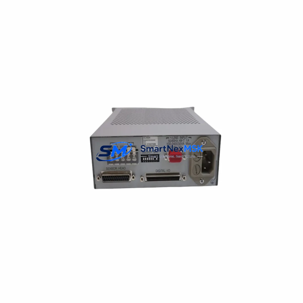
Anritsu KL2300A Retrofit-Ready Sensor Unit for KL2300 Series Control Systems
The Anritsu KL2300A is a sensor processing unit engineered for seamless integration into KL2300 Series temperature measurement and control systems. As legacy automation infrastructure ages and original components reach end-of-life, the KL2300A has become a critical retrofit solution for facilities managing older production lines, thermal processing equipment, and precision measurement stations. Whether you are executing a planned system upgrade or responding to an unplanned component failure, the KL2300A delivers verified compatibility with existing KL2300 Series architectures, minimizing engineering risk and reducing total downtime.
This unit is sourced from verified supply channels, individually inspected prior to shipment, and backed by a 12-month warranty covering manufacturing defects and functional performance. Each unit undergoes pre-shipment functional testing to confirm signal integrity, terminal continuity, and communication response before leaving our facility in Xiamen.
Upgrade Compatibility Table
| Parameter | KL2300A Specification | Retrofit Notes |
|---|---|---|
| Series Compatibility | KL2300 Series | Direct drop-in for KL2300 platform installations |
| Installation Type | Panel / DIN Rail Mount | Verify existing mounting bracket dimensions before installation |
| Communication Interface | RS-232 / RS-485 (model-dependent) | Confirm protocol settings match existing HMI or PLC configuration |
| Terminal Wiring | Screw-type terminal block | Cross-reference original wiring diagram; re-torque all terminals post-installation |
| Power Supply | 24 VDC / 100–240 VAC (model-dependent) | Verify power rail capacity before connecting; check existing PSU headroom |
| Replacement Recommendation | Direct replacement for KL2300A | No firmware modification required for same-series swap |
| Commissioning Focus | Sensor calibration, address assignment | Re-enter sensor type and range parameters after installation |
| Warranty | 12 Months | Covers manufacturing defects and functional performance failures |
Retrofit Planning for Existing Automation Systems
Integrating the KL2300A into an existing control architecture requires a structured approach to avoid configuration drift and signal errors. Before beginning the retrofit, engineers should document the current system topology, including the positions of all connected I/O modules, the addressing scheme used by the PLC or DCS controller, and the communication parameters configured in the HMI display.
In a typical KL2300 Series installation, the sensor processing unit interfaces with upstream temperature sensors and downstream control logic via a shared communication bus. When replacing the KL2300A, technicians must verify that the replacement unit’s communication address matches the original — particularly in multi-drop RS-485 networks where address conflicts can cause silent data errors or bus lockups. If the system uses a Mitsubishi MELSEC Q-series or FX-series PLC as the host controller, the ladder logic program should be reviewed to confirm that the sensor data register mapping remains consistent after the swap.
Power supply capacity is a frequent oversight in retrofit projects. The existing PSU — often a Omron S8VS or Phoenix Contact QUINT series unit — must have sufficient headroom to support the replacement module without voltage sag under load. Check the total current draw of all modules on the same power rail, including any additional I/O expansion modules, communication adapters, or relay output cards installed in the same control cabinet.
Terminal wiring should be re-verified against the original wiring diagram. In aging control cabinets, terminal blocks may have experienced oxidation or loose connections that were masked by the original module’s tolerance. This is an ideal time to inspect and replace any degraded Weidmüller or Phoenix Contact terminal blocks and to re-label all conductors for future maintenance clarity.
If the system includes a Proface or Weintek HMI, the screen configuration should be reviewed to confirm that all tag addresses referencing the KL2300A’s data registers remain valid. In some installations, the HMI communicates directly with the sensor unit rather than through the PLC, requiring independent address verification on the HMI side.
For systems that include a DeviceNet or PROFIBUS communication module in the same rack, confirm that the network configuration tool (such as RSNetWorx or Siemens STEP 7) reflects the updated node configuration after the KL2300A is installed. Failure to update the network configuration can result in communication faults that prevent the system from entering run mode.
Downtime Control During System Migration
Minimizing production downtime during a KL2300A replacement requires advance preparation and a disciplined commissioning sequence. Begin by creating a full backup of the host PLC program — whether stored on a Mitsubishi FX3U, Q02H, or equivalent controller — before any hardware is removed. This backup should include all data register values, parameter files, and communication settings, stored on a programming cable-connected laptop or a dedicated memory cassette.
Where possible, pre-configure the replacement KL2300A on a bench test setup before the scheduled maintenance window. Assign the correct communication address, configure the sensor input type and measurement range, and verify the output signal against a known reference before the unit is installed in the live cabinet. This approach reduces in-cabinet commissioning time to a terminal connection and a final functional check, typically achievable within 30 to 60 minutes for a single-unit swap.
During the cutover, maintain a clear record of the original terminal assignments and take photographs of the existing wiring before disconnection. After installation, power up the system in stages — energize the control power first, confirm the KL2300A initializes correctly, then restore the sensor inputs and verify the measured values against a calibrated reference instrument before returning the system to automatic control mode.
Post-installation, monitor the system for a minimum of one full production cycle to confirm stable operation, consistent sensor readings, and absence of communication alarms. Document the completed retrofit in the facility’s maintenance log, including the replacement unit’s serial number, installation date, and the name of the commissioning engineer.
Retrofit Support FAQ
Q: Is the KL2300A a direct drop-in replacement for the original unit?
A: Yes. The KL2300A is designed as a direct replacement for same-series KL2300 installations. Terminal pinout, mounting dimensions, and communication protocol are consistent with the original specification. Minor parameter re-entry (sensor type, range, address) is required after installation, as these settings are stored in the unit’s internal memory and are not transferred automatically.
Q: What communication protocols does the KL2300A support, and how do I verify compatibility with my existing HMI or PLC?
A: The KL2300A supports RS-232 and RS-485 serial communication depending on the specific model variant. Before ordering, confirm the communication interface type used in your installation. If your system uses a Modbus RTU protocol over RS-485, verify that the baud rate, parity, and stop bit settings match your existing network configuration. Our technical team can assist with protocol verification prior to shipment.
Q: What does the 12-month warranty cover, and what is the claims process?
A: The 12-month warranty covers manufacturing defects and functional performance failures under normal operating conditions. It does not cover damage resulting from incorrect installation, overvoltage, or physical impact. To initiate a warranty claim, contact our sales team with the unit serial number, purchase date, and a description of the fault. Replacement units are dispatched within 3 business days of claim approval.
Q: Can you provide pre-shipment test documentation for the KL2300A?
A: Yes. Each KL2300A unit undergoes functional testing prior to shipment, including signal output verification, terminal continuity check, and communication response test. A test report is available upon request and can be included with the shipment documentation for quality records and incoming inspection purposes.
© 2026 SMARTNEXMSK. All rights reserved.
Original Source: https://smartnexmsk.com
Contact: sales@smartnexmsk.com | +86 18259474341