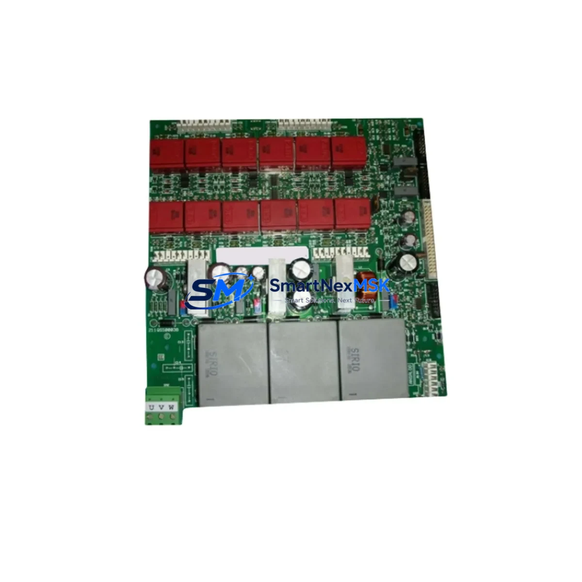
ANSALDO 211QS50003B Maintenance-Ready Spare for 211QS Automation
The ANSALDO 211QS50003B is an original SCR Gate Firing Board engineered for the 211QS series DC drive systems. In industrial environments where unplanned downtime translates directly into production loss, having a verified, maintenance-ready spare on hand is not optional — it is a core element of any responsible maintenance strategy. This board governs the precise gate pulse timing that controls SCR (Silicon Controlled Rectifier) firing sequences, making it a critical component in the power conversion stage of 211QS series drives. Failure of this board typically manifests as erratic motor speed, loss of torque control, drive fault codes, or complete drive shutdown. Rapid replacement with a tested original spare is the fastest path to restoring full system operation.
Sourced directly from verified supply channels, each 211QS50003B unit undergoes functional inspection and electrical verification prior to dispatch. The board is packaged with anti-static protection and ships with full traceability documentation. A 12-month warranty covers all units against manufacturing defects and functional failure under normal operating conditions. Whether you are managing a planned overhaul, responding to an emergency fault, or building a strategic spare parts inventory for aging 211QS installations, this board is ready for immediate deployment.
Spare Maintenance Table
| Parameter | Specification / Detail |
|---|---|
| Part Number | 211QS50003B |
| Brand | ANSALDO |
| Component Type | SCR Gate Firing Board |
| Compatible Series | ANSALDO 211QS Series DC Drives |
| Function | Gate pulse generation and timing control for SCR power bridge |
| Mounting | PCB board, direct replacement into 211QS drive chassis |
| Operating Environment | Industrial control cabinet, IP20 enclosure minimum recommended |
| Input Signal | Control signals from 211QS main control board |
| Output | Gate firing pulses to SCR thyristor bridge |
| Origin | Italy |
| Condition | Original spare, functionally tested before shipment |
| Warranty | 12 Months from date of shipment |
| Packaging | Anti-static bag, foam-protected carton |
| Lead Time | In-stock units ship within 2 business days |
| Maintenance Recommendation | Replace as part of scheduled drive overhaul or on fault diagnosis |
Maintenance Planning for Continuous Operation
When a 211QS50003B SCR Gate Firing Board is identified as the root cause of a drive fault, experienced maintenance engineers know that the board itself is rarely the only component that warrants attention. A systematic inspection of the surrounding electrical circuit is essential to prevent repeat failures and ensure the replacement board operates within its design parameters from day one.
Begin with the 211QS main control board, which generates the reference signals fed into the gate firing board. A degraded control board can produce irregular firing commands that stress and ultimately damage the gate firing circuitry. Simultaneously, inspect the SCR thyristor modules in the power bridge — a shorted or weakened thyristor can cause reverse voltage spikes that destroy gate firing boards prematurely. If the thyristors show signs of thermal stress or leakage current, replace them alongside the 211QS50003B.
The DC bus capacitor bank and associated snubber circuits should be checked for capacitance drift and ESR values. Degraded snubbers allow voltage transients to propagate back into the gate firing stage. The drive power supply board — which provides the isolated gate drive voltages — must also be verified; low or unstable auxiliary supply voltages are a common hidden cause of gate firing board failures.
On the signal side, inspect all fiber optic or pulse transformer couplers used to transmit gate signals in electrically isolated designs. Contaminated or aged couplers introduce timing jitter that can cause misfiring. The current feedback transducers (CTs) and voltage feedback circuits feeding the 211QS control loop should be calibrated and verified — incorrect feedback signals force the control board to issue abnormal firing commands.
For the broader control cabinet, check terminal blocks and wiring harnesses connecting the gate firing board to the thyristor gate leads. Loose or corroded connections cause intermittent misfiring that is difficult to diagnose and can damage the new board. Inspect the cabinet cooling fans and heat sink thermal interface on the SCR modules — thermal management is critical in high-current DC drive applications. Finally, review the drive parameter settings on the 211QS operator panel or HMI after replacement to confirm firing angle limits and current limits are correctly configured for the connected motor load.
Site Replacement Workflow
Step 1 — Fault Isolation: Use the 211QS drive diagnostic display or external fault logger to confirm the gate firing board as the fault source. Record all active fault codes before powering down.
Step 2 — Safe Isolation: Isolate the drive from the AC supply and DC bus. Verify zero voltage on the DC bus capacitors using a calibrated meter before opening the drive enclosure. Follow local LOTO (Lockout/Tagout) procedures.
Step 3 — Board Removal: Photograph the existing board orientation and connector positions before disconnection. Label all gate lead connections to the thyristor modules. Remove the 211QS50003B carefully, avoiding stress on the PCB.
Step 4 — Visual Inspection: Before installing the replacement, inspect the drive chassis for signs of arc damage, carbon tracking, or burnt components that may indicate a root cause beyond the board itself.
Step 5 — Installation: Install the replacement 211QS50003B, reconnect all gate leads in the correct sequence, and verify all connectors are fully seated. Restore any jumper or DIP switch settings that match the original board configuration.
Step 6 — Commissioning: Power up the drive in a controlled sequence. Monitor gate firing waveforms if test equipment is available. Run the motor at reduced load initially and verify speed regulation and current control before returning to full production load.
Step 7 — Documentation: Record the replacement in the equipment maintenance log, including the new board serial number, installation date, and post-replacement test results. Update the spare parts inventory accordingly.
Spare Parts Support FAQ
Q1: Is the 211QS50003B compatible with all variants of the ANSALDO 211QS series?
The 211QS50003B is the standard gate firing board for the 211QS series DC drive platform. Compatibility should be confirmed against the drive’s nameplate model number and the existing board part number before ordering. Minor hardware revisions within the 211QS series may use variant board suffixes — contact our technical team with your drive nameplate data for confirmation.
Q2: How is each board tested before shipment?
Every 211QS50003B unit is subject to functional electrical inspection prior to dispatch, including verification of gate pulse output integrity and isolation resistance checks. Units that do not meet specification are quarantined and not shipped. A test report is available on request for critical applications.
Q3: What does the 12-month warranty cover?
The 12-month warranty covers functional failure and manufacturing defects under normal industrial operating conditions. It does not cover damage resulting from incorrect installation, overvoltage events, or operation outside the drive’s rated parameters. Warranty claims are processed with return of the defective unit for inspection.
Q4: Can you support long-term or blanket spare parts orders for 211QS fleet maintenance?
Yes. For customers managing multiple 211QS installations or planning multi-year maintenance programs, we support scheduled release orders, reserved stock arrangements, and priority allocation. Contact our sales team to discuss a supply agreement tailored to your maintenance cycle and fleet size.
© 2026 SMARTNEXMSK. All rights reserved.
Original Source: https://smartnexmsk.com
Contact: sales@smartnexmsk.com | +86 18259474341