APTECH AP1406TSM-2PW-MV4-MVE4-P Spare for AP1400 Automation: Spare Parts Replacement & Industrial Downtime Risk Control
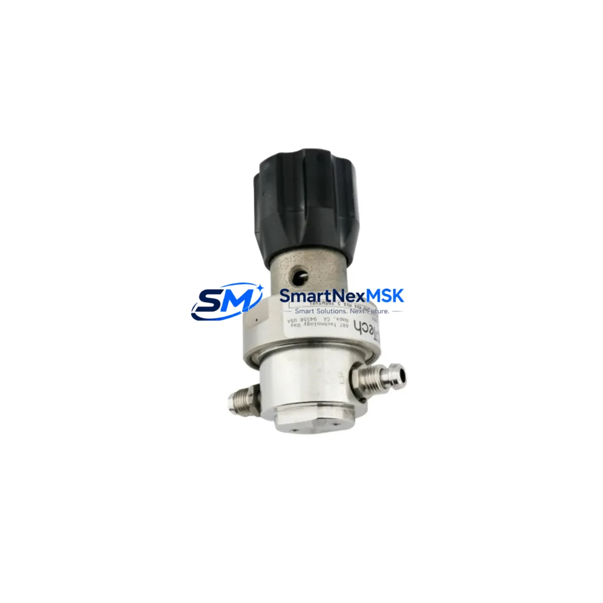
The APTECH AP1406TSM-2PW-MV4-MVE4-P is a high-purity pressure regulator engineered for precision gas control in semiconductor fabrication, specialty gas distribution, and industrial automation systems built on the AP1400 series platform. As a maintenance-ready original spare, this unit is stocked and tested to support rapid field replacement, minimizing unplanned downtime in critical process environments. Whether you are executing a scheduled turnaround, responding to an emergency shutdown, or building out your facility’s spare parts inventory, the AP1406TSM-2PW-MV4-MVE4-P delivers the dimensional and functional compatibility required for a direct drop-in installation without system reconfiguration.
Maintenance engineers working with APTECH AP1400 series gas panels understand that regulator performance directly impacts process yield and safety. A degraded or failed pressure regulator can cascade into flow instability, contamination events, or interlock trips across the entire gas delivery system. Stocking the AP1406TSM-2PW-MV4-MVE4-P as a certified spare eliminates the lead-time risk associated with sourcing this component during an active fault condition. Each unit shipped by SMARTNEXMSK undergoes pre-shipment functional verification and is backed by a 12-month warranty covering manufacturing defects and performance deviations from published specifications.
Spare Maintenance Table
| Parameter | Specification / Detail |
|---|---|
| Part Number | AP1406TSM-2PW-MV4-MVE4-P |
| Brand | APTECH |
| Series | AP1400 |
| Product Type | High-Purity Pressure Regulator |
| Body Material | 316L Stainless Steel (electropolished) |
| Inlet / Outlet Connection | MV4 / MVE4 (VCR-compatible face-seal fittings) |
| Actuation | 2PW — Two-stage piston-actuated, panel-mount configuration |
| Seat Configuration | TSM — Thermally stabilized metal seat |
| Suffix -P | Particle-tested, cleaned for high-purity gas service |
| Inlet Pressure Range | Up to 3000 psig (207 bar) — typical AP1400 series rating |
| Outlet Pressure Range | 0–250 psig adjustable (application-dependent) |
| Compatible Media | High-purity inert and reactive specialty gases (N₂, Ar, H₂, SiH₄, NF₃, etc.) |
| Operating Temperature | 0°C to 65°C ambient; process gas temperature per media spec |
| Leak Integrity | < 1×10⁻⁹ std cc/sec He (factory tested) |
| Weight | 2,600 g (as shipped) |
| Origin | United States |
| Compatibility | Direct replacement for AP1400 series panel assemblies; cross-compatible with AP1402TS-2PW-MVE4-MVE4-P configurations |
| Installation | Panel-mount; VCR face-seal inlet/outlet; torque to APTECH specification |
| Maintenance Interval | Inspect diaphragm and seat annually or per process cycle count |
| Warranty | 12 Months — Manufacturing defects and performance deviation |
| Pre-Shipment Test | Functional leak test, set-point verification, particle count |
| Lead Time | In-stock; ships within 3–5 business days |
Maintenance Planning for Continuous Operation
When replacing the AP1406TSM-2PW-MV4-MVE4-P in a live gas panel, a disciplined maintenance engineer does not stop at the regulator itself. The AP1400 series gas delivery system is an integrated assembly, and component wear rarely occurs in isolation. During the same maintenance window, inspect and consider replacing the following associated components to restore full system integrity:
Begin with the upstream isolation valve — typically an APTECH AP1000 series or equivalent high-purity manual or pneumatic valve — to confirm it seats cleanly and holds pressure before the new regulator is pressurized. Check the VCR face-seal gaskets (MV4 and MVE4 fittings) at both the inlet and outlet; these single-use metal gaskets must be replaced any time a connection is broken, and reusing them is a common source of post-maintenance leaks. Inspect the downstream flow controller or mass flow controller (MFC) — such as an MKS or Brooks instrument installed in the same gas stick — for drift or contamination that may have been masked by regulator instability.
Review the panel purge valve assembly and associated pneumatic actuator solenoids (24 VDC or 110 VAC, depending on panel design) for response time and seal condition. If the gas panel feeds a PLC-controlled interlock system, verify that the pressure transducer or transmitter on the outlet side — commonly a 4–20 mA or 0–10 V signal device — is reading accurately after regulator replacement, as a faulty transducer can generate nuisance trips or mask real over-pressure events. Check the stainless steel tubing and compression fittings downstream for stress cracks or corrosion, particularly in high-cycle or thermally cycled environments.
For panels integrated into a DCS or PLC architecture, confirm that the I/O module receiving the pressure signal — whether a Siemens ET 200SP analog input module, a Rockwell 1756-IF8 ControlLogix card, or equivalent — is logging correctly and that alarm setpoints are re-validated after the regulator set-point is adjusted. If the system uses a signal isolator or barrier between the field transmitter and the control system, verify isolation integrity. Finally, inspect the panel enclosure seals and purge fittings to ensure the control cabinet environment remains within specification for the installed electronics.
Site Replacement Workflow
Step 1 — Isolation and Depressurization: Close the upstream cylinder valve and actuate the panel purge sequence to vent residual gas from the regulator body. Confirm zero pressure on both inlet and outlet gauges or transducers before breaking any connection.
Step 2 — Connection Disassembly: Using calibrated torque tools, loosen the MV4 inlet and MVE4 outlet VCR nuts. Remove the old metal gaskets and inspect the gland faces for scoring or contamination. Do not reuse gaskets.
Step 3 — Regulator Removal and Inspection: Remove the AP1406TSM-2PW-MV4-MVE4-P from the panel mount. Inspect the mounting bracket, panel cutout, and adjacent components for signs of corrosion, vibration damage, or gas staining that may indicate a prior leak path.
Step 4 — New Unit Installation: Install fresh VCR gaskets on both connections. Mount the replacement AP1406TSM-2PW-MV4-MVE4-P and torque VCR nuts to APTECH-specified values (typically 1/8 turn past finger-tight for stainless glands). Do not over-torque.
Step 5 — Leak Test and Set-Point Verification: Pressurize slowly with an inert purge gas (N₂ or Ar). Perform a helium leak check or bubble test at all disturbed connections. Adjust the regulator set-point to the process-required outlet pressure and confirm stability under flow conditions.
Step 6 — System Recommission: Restore the process gas supply, verify PLC/DCS pressure readings match the local gauge, confirm alarm setpoints, and document the replacement in the maintenance management system (CMMS). Update the spare parts inventory to trigger reorder of the consumed AP1406TSM-2PW-MV4-MVE4-P unit.
This workflow is applicable whether you are replacing an end-of-life unit on a scheduled basis or executing an emergency swap to recover from an unplanned shutdown. The AP1406TSM-2PW-MV4-MVE4-P is dimensionally identical to earlier AP1400 series regulators, making it a direct mechanical replacement that preserves system compatibility without panel modification.
Spare Parts Support FAQ
Q1: Is the AP1406TSM-2PW-MV4-MVE4-P a direct replacement for the AP1402TS-2PW-MVE4-MVE4-P?
Yes. The AP1406TSM and AP1402TS share the same AP1400 series panel-mount footprint and VCR connection geometry. The AP1406TSM incorporates a thermally stabilized metal seat (TSM) and updated diaphragm materials relative to earlier AP1402 variants, making it a performance-equivalent or superior drop-in replacement. Confirm outlet pressure set-point after installation, as the TSM seat may exhibit slightly different droop characteristics at low flow rates.
Q2: What is the recommended spare parts stocking strategy for AP1400 series gas panels?
For facilities operating multiple AP1400 series gas sticks, we recommend maintaining a minimum of one AP1406TSM-2PW-MV4-MVE4-P per five installed regulators as a rotating spare. Pair this with a stock of MV4 and MVE4 VCR gaskets (minimum 10 per connection type), upstream isolation valve spares, and at least one spare pressure transducer per panel type. This inventory posture supports same-shift emergency replacement without waiting for procurement lead times.
Q3: How is each unit tested before shipment?
Every AP1406TSM-2PW-MV4-MVE4-P shipped by SMARTNEXMSK undergoes a pre-shipment protocol that includes: (1) helium leak test at rated inlet pressure to verify <1×10⁻⁹ std cc/sec integrity; (2) set-point functional test across the outlet pressure range; (3) particle count verification per SEMI F57 or equivalent high-purity cleanliness standard; and (4) visual inspection of all wetted surfaces and connection glands. A test certificate is available upon request.
Q4: What does the 12-month warranty cover, and how is a warranty claim processed?
The 12-month warranty covers manufacturing defects, seat leakage beyond specification, and diaphragm failure under normal operating conditions. It does not cover damage resulting from improper installation, incompatible media, over-pressurization beyond rated inlet pressure, or physical impact. To initiate a warranty claim, contact SMARTNEXMSK with the original order number, a description of the failure mode, and photographic documentation. Replacement units are dispatched upon claim approval, typically within 5 business days.
© 2026 SMARTNEXMSK. All rights reserved.
Original Source: https://smartnexmsk.com
Contact: sales@smartnexmsk.com | +86 18259474341