ASIPRA 211QS10540C Maintenance-Ready Spare for 211QS Automation
The ASIPRA 211QS10540C is an original PLC control module engineered for the 211QS series automation platform. For maintenance engineers managing aging control systems, unplanned downtime caused by a failed PLC module is one of the most costly disruptions on the plant floor. Stocking the 211QS10540C as a certified spare ensures that when a fault occurs — whether during a scheduled shutdown or an emergency callout — your team can execute a clean, validated replacement without waiting days for procurement. This module is sourced directly from authorized supply channels, fully tested prior to shipment, and backed by a 12-month warranty, giving both maintenance and procurement teams the confidence to hold it on the shelf and deploy it on demand.
The 211QS10540C is designed for demanding industrial environments where signal integrity, thermal stability, and long-term firmware compatibility are non-negotiable. Whether you are maintaining a legacy 211QS-based control cabinet or extending the operational life of an older automation system, this module delivers the original electrical performance and form-factor fit required for a drop-in replacement. Procurement engineers will appreciate the long-term supply commitment: we maintain buffer stock specifically for 211QS series components to support customers with multi-year maintenance contracts and annual spare parts budgets.
Spare Maintenance Table
| Parameter | Specification |
|---|---|
| Part Number / SKU | 211QS10540C |
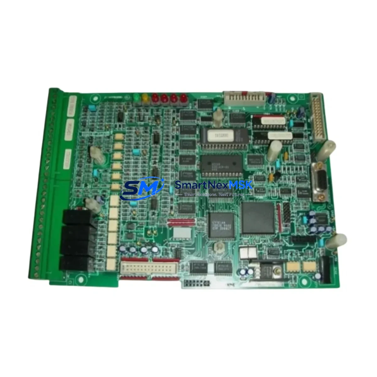
| Brand | ASIPRA |
| Series | 211QS |
| Product Type | PLC Control Module |
| Origin | China (CN) |
| Compatibility | ASIPRA 211QS series PLC platforms; direct replacement for same-series modules |
| Installation | DIN rail or panel mount; refer to 211QS series installation manual for slot assignment |
| Operating Environment | Industrial control cabinet; standard IEC 61131-2 operating conditions |
| Communication | Compatible with 211QS series backplane and I/O bus architecture |
| Pre-shipment Testing | Full functional test performed before dispatch |
| Warranty | 12 Months from date of shipment |
| Maintenance Recommendation | Inspect connectors and backplane contacts during annual shutdown; verify firmware version compatibility before installation |
| Lead Time | In-stock; ships within 1–3 business days |
Maintenance Planning for Continuous Operation
A PLC control module like the 211QS10540C does not operate in isolation. When planning a replacement or conducting a control cabinet inspection, experienced maintenance engineers know that the surrounding components must be evaluated at the same time to prevent repeat failures and ensure system stability after the module swap.
Start with the 24VDC power supply module feeding the 211QS rack — a degraded power supply is a common root cause of intermittent PLC faults and should be load-tested before the new module is commissioned. Check the backplane or rack assembly for bent connector pins, oxidation, or mechanical damage that could cause poor contact with the replacement module. If the 211QS system uses a dedicated CPU or processor module, verify that its firmware is compatible with the 211QS10540C revision you are installing.
On the I/O side, inspect the digital input (DI) and digital output (DO) modules in adjacent slots — a shorted field device connected to a DO channel is a frequent cause of module damage and may have contributed to the original failure. Similarly, review the analog input (AI) modules for signal drift or calibration errors that could indicate upstream sensor or wiring issues. Terminal blocks and field wiring connectors should be re-torqued and inspected for insulation breakdown, especially in high-vibration or high-temperature environments.
For systems with networked I/O or remote stations, check the PROFIBUS DP or Ethernet communication module for error counters and cable integrity — a communication fault can mask or mimic a control module failure. If the cabinet includes signal isolators or signal conditioners between field instruments and the PLC, verify their output ranges are within specification. Miniature circuit breakers (MCBs) and fuse holders protecting the I/O circuits should also be tested for correct trip characteristics. Finally, if an HMI panel is connected to the 211QS system, confirm that the communication driver and tag database remain intact after the module replacement to avoid operator interface errors on restart.
Building a structured spare parts kit around the 211QS10540C — including at minimum one spare power supply, one spare CPU module, and a set of I/O module spares matched to your critical process loops — is the most effective strategy for reducing mean time to repair (MTTR) and protecting production continuity.
Site Replacement Workflow
Step 1 — Preparation: Before arriving on site, confirm the exact revision and firmware version of the installed 211QS10540C by checking the module label and the system configuration backup. Ensure the replacement unit matches the revision or is confirmed backward-compatible by the manufacturer’s documentation.
Step 2 — Safe Isolation: Follow your site’s lockout/tagout (LOTO) procedure. De-energize the control cabinet and discharge any residual voltage on the backplane before removing the faulty module. Do not hot-swap unless the 211QS platform explicitly supports hot-swap for this module type.
Step 3 — Module Removal and Inspection: Remove the 211QS10540C by releasing the locking mechanism and sliding it out of the rack slot. Inspect the backplane connector for damage. Clean the slot contacts with an appropriate contact cleaner if oxidation is present.
Step 4 — Installation: Seat the replacement 211QS10540C firmly into the rack slot until the locking tab engages. Reconnect all field wiring connectors, verifying terminal assignments against the original wiring diagram. Re-torque terminal screws to the specified torque value.
Step 5 — Power-Up and Verification: Restore power and observe the module’s status LEDs. Load or restore the PLC program from the configuration backup. Perform an I/O force test on critical channels to confirm correct signal mapping before returning the system to automatic operation.
Step 6 — Documentation: Record the replacement in the maintenance log, including the date, replaced module serial number, new module serial number, and the technician’s name. Update the spare parts inventory to trigger a replenishment order for the next 211QS10540C unit.
Spare Parts Support FAQ
Q1: Is the 211QS10540C a direct drop-in replacement for the original installed module?
Yes. The 211QS10540C is an original ASIPRA part designed for the 211QS series platform. It is a form-fit-function replacement for the same SKU. If your installed module carries a different revision suffix, contact our technical team to confirm cross-compatibility before ordering.
Q2: What does the 12-month warranty cover?
The 12-month warranty covers manufacturing defects and functional failures under normal operating conditions from the date of shipment. It does not cover damage caused by incorrect installation, overvoltage events, or physical mishandling. All units are functionally tested before dispatch, and a test report is available upon request.
Q3: How should I manage 211QS10540C inventory for a multi-site operation?
We recommend holding a minimum of one unit per control system as a hot spare, with a reorder point triggered when the spare is consumed. For facilities with three or more 211QS-based systems, a centralized regional spare pool of two to three units is a cost-effective strategy. We support blanket purchase orders and scheduled delivery programs for customers with annual maintenance budgets.
Q4: Can you supply the 211QS10540C with a certificate of conformance or test report?
Yes. A certificate of conformance (CoC) and functional test report are available upon request at the time of order. These documents support incoming inspection procedures and are accepted by most quality management systems operating under ISO 9001 or equivalent standards.
© 2026 SMARTNEXMSK. All rights reserved.
Original Source: https://smartnexmsk.com
Contact: sales@smartnexmsk.com | +86 18259474341