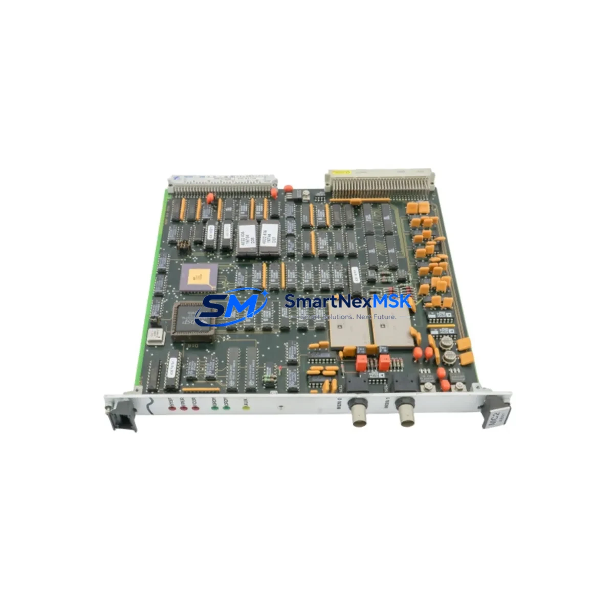
ASML MC2 AB41 4022.436.2693 Retrofit-Ready PCB Control Board for Legacy System Upgrades
The ASML MC2 AB41 4022.436.2693 is a retrofit-ready PCB control board engineered for seamless integration into existing ASML MC2 series lithography and precision motion control systems. As original ASML MC2 platform components approach end-of-life and spare part availability tightens, this board provides a verified, wiring-compatible replacement path that allows facilities to extend operational life, reduce unplanned downtime, and defer costly full-system replacements.
Whether you are managing a scheduled maintenance window, responding to an unplanned board failure, or executing a phased control system modernization, the AB41 4022.436.2693 is designed to drop into your existing MC2 control cabinet with minimal re-engineering. The board maintains compatibility with the MC2 backplane interface, preserving existing terminal wiring, I/O addressing, and communication link configurations that your engineering team has already validated in the field.
Upgrade Compatibility Table
| Parameter | Details |
|---|---|
| Replacement Target | ASML MC2 AB41 4022.436.2693 (OEM original) |
| Compatible Platform | ASML MC2 Series Control Systems |
| Backplane Interface | MC2 standard backplane connector — direct fit, no adapter required |
| Terminal Wiring | Wiring-compatible with existing MC2 cabinet harness; no re-termination required under standard retrofit conditions |
| Communication Compatibility | Supports existing MC2 internal communication links; verify protocol version with your system integrator prior to installation |
| Installation Requirement | Standard MC2 rack/chassis mounting; confirm slot address assignment before power-up |
| Module Address Configuration | Address must be confirmed and matched to original board configuration in system software prior to commissioning |
| Commissioning Note | HMI screen mapping and program logic verification recommended after board swap; retain original program backup before replacement |
| Pre-Shipment Testing | Each unit undergoes functional verification and burn-in testing before dispatch |
| Warranty | 12-Month Warranty — covers manufacturing defects and functional failures under normal operating conditions |
Retrofit Planning for Existing Automation Systems
Successful retrofit of the MC2 AB41 4022.436.2693 begins well before the board arrives on-site. A structured pre-replacement audit of the control cabinet is essential. Engineers should document the existing power supply rail voltages feeding the MC2 backplane — typically the MC2 system power module provides regulated DC rails to all installed boards, and confirming that the power supply capacity is sufficient to support the replacement board under full I/O load is a critical first step. If the existing MC2 power supply module is aging or showing voltage drift, replacing it concurrently with the control board eliminates a common source of post-retrofit instability.
Terminal block wiring should be photographed and labeled before any board removal. The MC2 series uses a structured terminal assignment scheme, and even minor wiring transpositions during reinstallation can cause I/O mapping errors that are time-consuming to diagnose. If the system includes MC2 digital input modules or MC2 analog output modules sharing the same rack, their slot addresses and I/O configurations should be recorded and verified against the control program’s hardware configuration table.
For systems that include an MC2 communication interface module — whether for PROFIBUS, DeviceNet, or a proprietary ASML fieldbus link — the communication link parameters (node address, baud rate, termination resistor status) must be documented before the retrofit and restored identically after board replacement. A communication link misconfiguration is one of the most common causes of extended commissioning time following a board swap.
If the control system interfaces with an HMI panel — such as an ASML-integrated operator terminal or a third-party SCADA workstation — the HMI screen mapping tied to the MC2 control board’s data tags should be reviewed. In some MC2 configurations, the AB41 board manages specific motion or process data blocks that are directly referenced in HMI display pages. Confirming that these data block addresses remain consistent after the board replacement prevents HMI communication faults during restart.
Where the MC2 system is connected to a broader automation network — for example, coordinating with upstream or downstream equipment via an MC2 network communication card — the network topology diagram should be reviewed to confirm that the replacement board does not alter the system’s network node identity. In multi-axis or multi-zone MC2 installations, each control board may carry a unique node assignment that must be preserved.
For facilities managing a larger modernization project — such as migrating from an MC2 platform to a newer control architecture — the AB41 4022.436.2693 can serve as a bridge component, maintaining production continuity on the MC2 system while the new control platform is being configured, tested, and validated in parallel. This staged approach, sometimes called a parallel-run migration, is widely used in semiconductor and precision manufacturing environments where production continuity requirements make hard-cutover migrations impractical.
Stock availability of the MC2 AB41 4022.436.2693 is maintained to support both emergency replacement and planned maintenance schedules. Units are dispatched with full pre-shipment test documentation, and the 12-month warranty covers functional failures under normal operating conditions from the date of receipt.
Downtime Control During System Migration
Minimizing downtime during an MC2 control board replacement requires a disciplined pre-work protocol. Before initiating any board removal, the original control program should be backed up from the MC2 controller — whether stored on the MC2 CPU module’s onboard memory or on an external programming device connected via the MC2 programming cable interface. Losing the validated program during a board swap is one of the most costly and avoidable retrofit failures.
A recommended sequence for downtime control is: (1) complete pre-replacement documentation including wiring photos, address tables, and communication parameters; (2) stage the replacement MC2 AB41 4022.436.2693 board on an ESD-safe surface and verify its physical condition and connector integrity; (3) execute a controlled system shutdown following the MC2 platform’s recommended power-down sequence to avoid backplane transients; (4) perform the board swap with attention to backplane connector seating and any retention hardware; (5) restore power and verify that the MC2 power supply module is delivering correct rail voltages before enabling the control program; (6) reload or verify the control program, confirm I/O addressing, and perform a controlled restart with field devices in a safe state.
For systems where even brief production interruption is costly, a pre-staged spare board strategy — maintaining one verified MC2 AB41 4022.436.2693 unit in the facility’s spare parts inventory — is the most effective downtime mitigation. Combined with a documented replacement procedure, this approach can reduce mean time to repair (MTTR) for an MC2 board failure to under two hours in most installations.
The 12-month warranty on each unit provides additional assurance that the replacement board will perform reliably through the initial post-retrofit operating period, covering the highest-risk phase of any control system component replacement.
Retrofit Support FAQ
Q: Is the MC2 AB41 4022.436.2693 a direct drop-in replacement for the original ASML board?
A: Yes, under standard MC2 retrofit conditions. The board is designed to be wiring-compatible and backplane-compatible with the original MC2 AB41 4022.436.2693. Module address configuration and communication link parameters should be verified and matched to the original board settings before commissioning. If your system has been modified from its original MC2 configuration, consult your system integrator to confirm compatibility.
Q: What commissioning steps are required after installing the replacement board?
A: After physical installation, verify that the MC2 power supply is delivering correct voltages to the backplane. Confirm the module slot address matches the original configuration. Reload or verify the control program, check I/O mapping against the original hardware configuration table, and confirm communication link parameters. If the system includes an HMI, verify that data tag references to the AB41 board are resolving correctly before returning the system to production.
Q: Does the board ship with a test report, and what does the 12-month warranty cover?
A: Each MC2 AB41 4022.436.2693 unit is functionally tested and burn-in verified before dispatch. A pre-shipment test record is included with the unit. The 12-month warranty covers manufacturing defects and functional failures under normal operating conditions from the date of receipt. It does not cover damage resulting from incorrect installation, overvoltage events, or physical mishandling.
Q: Can this board be used as a long-term spare for facilities managing multiple MC2 systems?
A: Yes. Facilities operating multiple MC2 platforms are encouraged to maintain a verified spare inventory of the AB41 4022.436.2693 to support rapid response to unplanned failures. Units are stored and dispatched under controlled conditions to preserve board integrity. Contact our sales team to discuss volume availability and lead times for multi-unit spare stock orders.
© 2026 SMARTNEXMSK. All rights reserved.
Original Source: https://smartnexmsk.com
Contact: sales@smartnexmsk.com | +86 18259474341