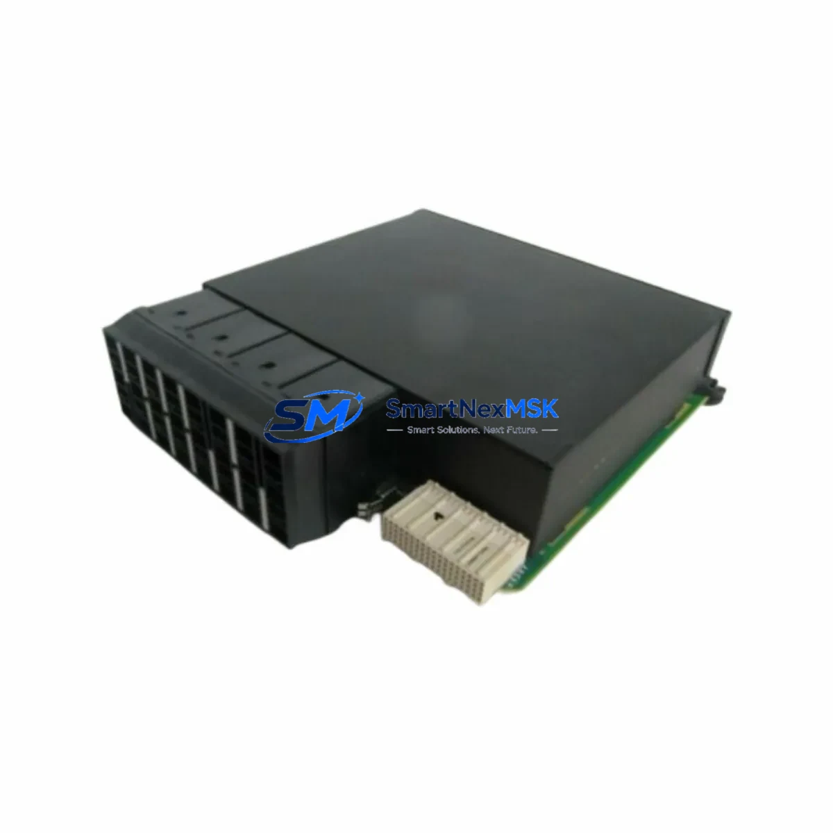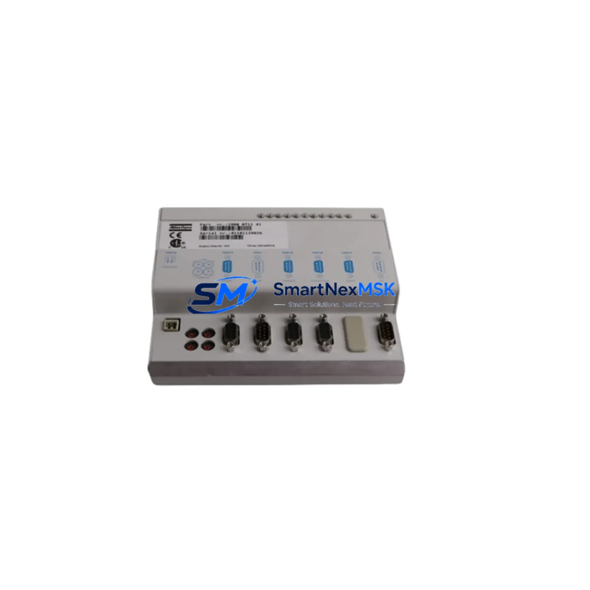
Atlas Copco 1900071141 Maintenance-Ready Spare for Fieldbus Automation
The Atlas Copco 1900071141 is an original fieldbus communication module designed for integration within Atlas Copco assembly automation and tightening control systems. For maintenance engineers managing production uptime and procurement engineers building strategic spare parts inventories, this module represents a critical node in the communication backbone of any Atlas Copco-based control architecture. Unplanned failure of a fieldbus communication module can halt an entire assembly line within minutes — having a verified, tested replacement on the shelf is the most effective form of downtime insurance available.
This unit is sourced as an original Atlas Copco spare, inspected prior to dispatch, and backed by a 12-month warranty covering manufacturing defects and functional performance. It is suitable for direct replacement in existing Atlas Copco controller cabinets without firmware reconfiguration in most standard deployments, significantly reducing mean time to repair (MTTR) during unplanned outages.
Spare Maintenance Table
| Parameter | Specification |
|---|---|
| Part Number / SKU | 1900071141 |
| Brand | Atlas Copco |
| Product Type | Fieldbus Communication Module |
| Series Compatibility | Atlas Copco Power Focus / Tensor Series Assembly Controllers |
| Communication Protocol | Fieldbus (DeviceNet / PROFIBUS / EtherNet/IP — confirm with system documentation) |
| Installation Type | Internal module slot, controller cabinet |
| Origin | Sweden (SE) |
| Weight | 280 g |
| Application Environment | Industrial assembly, tightening systems, automotive manufacturing |
| Maintenance Recommendation | Inspect communication LEDs and bus termination resistors at each planned maintenance interval; replace if bus error rate exceeds threshold |
| Warranty | 12 Months — covers manufacturing defects and functional performance |
| Pre-shipment Testing | Functional communication test performed before dispatch |
| Condition | Original spare — new or refurbished to OEM specification |
Maintenance Planning for Continuous Operation
When a fieldbus communication module such as the 1900071141 is flagged for replacement during a planned shutdown or emergency callout, experienced maintenance engineers know that the communication fault is rarely an isolated event. A systematic inspection of the surrounding electrical environment is essential to prevent repeat failures and ensure the system returns to full operational status.
Begin by verifying the 24 VDC power supply module feeding the controller rack — voltage sag or ripple is a leading cause of premature communication module failure. Check the fieldbus cable termination resistors at both ends of the bus segment; a missing or degraded terminator generates reflections that corrupt data frames and can be misdiagnosed as a module fault. Inspect the I/O expansion modules connected downstream on the same bus segment, as a failing I/O node can drag the entire segment into error state.
For Atlas Copco Power Focus and Tensor series controllers, also inspect the tightening controller main board and its internal backplane connectors — oxidized or loose backplane contacts are a common root cause of intermittent communication faults. The Ethernet switch or hub serving the controller network should be checked for port errors if the system uses EtherNet/IP topology. Review the signal isolation barriers on any analog feedback lines entering the controller, as ground loops introduced through poorly isolated signals can induce noise on the fieldbus.
Procurement engineers should ensure the spare parts cabinet includes at minimum: one spare 1900071141 communication module, a spare power supply unit matched to the controller voltage specification, a set of bus termination plugs, spare fieldbus connector housings with pre-terminated leads, and a replacement controller memory card or parameter backup device to restore tool programs after a controller swap. For sites running legacy Atlas Copco systems, maintaining a spare HMI operator panel or handheld programming terminal is also advisable, as these are frequently discontinued and difficult to source on short notice.
Where the 1900071141 is used in multi-spindle tightening cells, coordinate replacement with a check of the spindle drive modules and their associated torque transducer signal cables — mechanical stress on cable runs near moving tooling is a frequent source of intermittent faults that surface only under production load.
Site Replacement Workflow
Step 1 — Isolate and document: Before removing the 1900071141, record the current fieldbus node address, baud rate setting, and any DIP switch or rotary switch positions on the module. Photograph the wiring and connector orientation. Export or back up the controller parameter set if the system supports it.
Step 2 — Power down safely: De-energize the controller cabinet following the site lockout/tagout (LOTO) procedure. Confirm zero-energy state with a calibrated voltage tester before opening the cabinet.
Step 3 — Remove and inspect: Extract the faulty module from its slot. Inspect the backplane connector pins for damage, corrosion, or debris. Clean the slot with compressed air if required.
Step 4 — Install replacement: Seat the new 1900071141 firmly into the module slot. Reconnect all fieldbus cables and verify termination. Set node address and baud rate to match the documented values from Step 1.
Step 5 — Power up and verify: Restore power and observe the module status LEDs. A solid green bus status LED indicates successful network integration. Confirm communication with the host controller and all downstream nodes before resuming production.
Step 6 — Log and update records: Record the replacement in the site maintenance management system (CMMS). Update the spare parts inventory and initiate a reorder for the consumed spare to maintain buffer stock levels.
This workflow is applicable to both planned maintenance windows and emergency breakdown scenarios. The structured approach minimizes re-work risk and ensures the system is returned to a verified, documented state — reducing the probability of a repeat callout within the same maintenance cycle.
Spare Parts Support FAQ
Q1: What is the warranty coverage for the Atlas Copco 1900071141?
All units are covered by a 12-month warranty from the date of shipment. The warranty covers manufacturing defects and confirmed functional failures under normal operating conditions. Each unit undergoes a functional communication test prior to dispatch to verify performance before it leaves our facility.
Q2: How do I confirm compatibility with my existing Atlas Copco controller?
The 1900071141 is designed for Atlas Copco Power Focus and Tensor series assembly controllers. To confirm compatibility, cross-reference the part number against your controller’s spare parts list or the system’s bill of materials. If you have the controller model number and software version, our technical team can verify compatibility before order placement.
Q3: Can this module replace older or discontinued Atlas Copco fieldbus modules?
In many cases, yes. Atlas Copco has maintained backward compatibility across several generations of fieldbus modules within the Power Focus and Tensor platform. However, firmware version and hardware revision should be confirmed against the replacement module specification. Contact us with your existing module’s label information for a compatibility assessment.
Q4: What is your lead time and long-term supply availability?
Standard in-stock units ship within 1–3 business days. For sites requiring ongoing supply agreements or buffer stock arrangements for legacy systems, we offer long-term sourcing support. We maintain supplier relationships that allow us to source original and OEM-equivalent spares for Atlas Copco systems well beyond the standard product lifecycle, supporting old-system life extension programs for facilities that cannot justify a full controller upgrade.
© 2026 SMARTNEXMSK. All rights reserved.
Original Source: https://smartnexmsk.com
Contact: sales@smartnexmsk.com | +86 18259474341