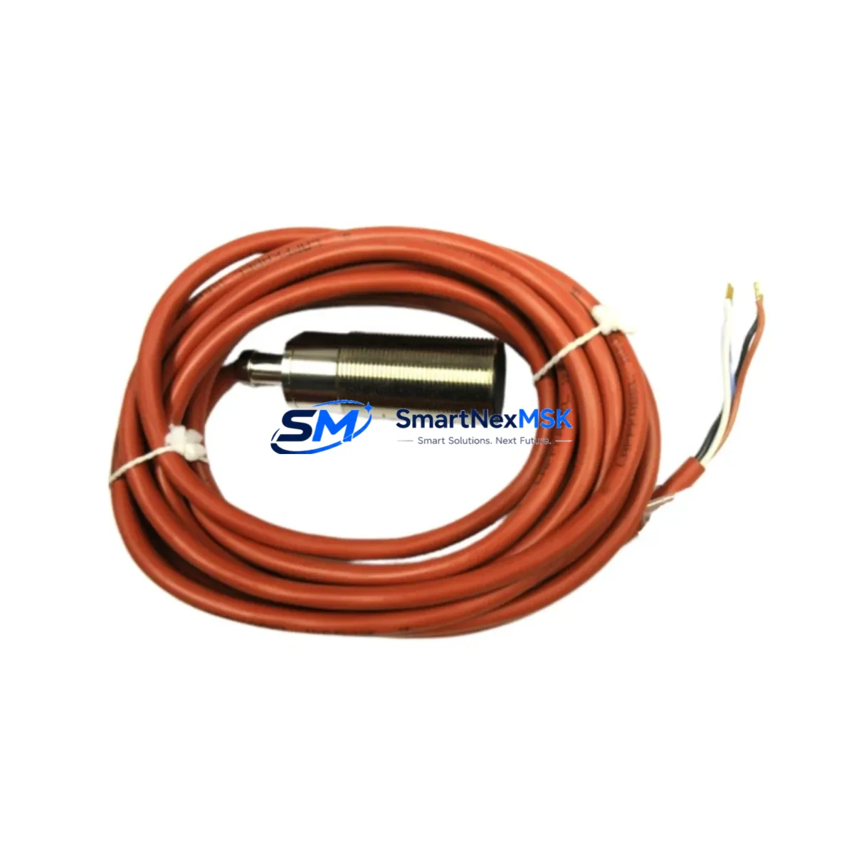
Balluff BES 516-114-SA1-05 Maintenance-Ready Spare for BES 516 Automation
The Balluff BES 516-114-SA1-05 is a high-reliability inductive proximity sensor engineered for continuous-duty industrial automation environments. As a maintenance-ready original spare, this unit is stocked and tested to support rapid field replacement, minimizing unplanned downtime in production lines, conveyor systems, machine tool enclosures, and automated assembly cells. Sourced directly from authorized supply channels, each unit ships with full traceability and a 12-month warranty covering manufacturing defects and functional performance.
For maintenance engineers managing aging BES 516 series installations, the BES 516-114-SA1-05 offers a direct, pin-compatible replacement that eliminates the need for wiring modifications or PLC parameter changes. Its M12 connector interface and standardized output characteristics ensure seamless integration into existing control architectures without additional commissioning overhead. Procurement engineers can rely on confirmed long-term stock availability and tested-before-dispatch protocols to support both emergency callouts and scheduled preventive maintenance programs.
Spare Maintenance Table
| Parameter | Specification |
|---|---|
| SKU / Part Number | BES 516-114-SA1-05 |
| Brand | Balluff |
| Series | BES 516 |
| Product Type | Inductive Proximity Sensor |
| Sensing Range | Approx. 1.5 mm (flush-mount, standard target) |
| Output Type | PNP / NPN (confirm per variant suffix) |
| Supply Voltage | 10–30 V DC |
| Connection | M12 connector, 4-pin |
| Housing | Cylindrical, stainless steel, flush-mount |
| Protection Rating | IP67 |
| Operating Temperature | -25 °C to +70 °C |
| Country of Origin | Germany |
| Compatibility | Direct replacement for BES 516 series installations |
| Warranty | 12 Months — covers manufacturing defects and functional performance |
| Shipping | Tested before dispatch; express options available |
Maintenance Planning for Continuous Operation
When replacing the BES 516-114-SA1-05 during a scheduled inspection or emergency callout, a thorough review of the surrounding electrical circuit is essential to prevent repeat failures and ensure system integrity. Begin by inspecting the M12 sensor cable and connector for insulation damage, moisture ingress, or pin corrosion — a degraded cable assembly such as a BAM 0M-M12-SA1-05 or equivalent Balluff cable set is a frequent root cause of sensor signal loss that is often misdiagnosed as sensor failure.
Check the 24 V DC power supply rail feeding the sensor circuit. Voltage ripple or transient spikes from adjacent motor drives or solenoid valves can shorten sensor service life; a dedicated power filter or surge suppressor on the supply line is recommended. Verify the input card on the connected PLC or safety controller — Balluff BES 516 series sensors are commonly wired into Siemens S7-300/S7-400 digital input modules (e.g., SM 321 series) or equivalent I/O modules from Beckhoff, Mitsubishi, or Omron. Confirm that the input channel threshold voltage and filter time settings match the sensor’s output characteristics.
For installations within a control cabinet, inspect the terminal blocks on the sensor circuit — Phoenix Contact or Weidmüller screw-clamp terminals should be checked for loose connections and oxidation. If the sensor feeds a safety relay module (e.g., a Pilz PNOZ or Schmersal SRB series), verify that the relay’s input impedance and response time remain within specification. In systems using a fieldbus interface such as Balluff’s BNI IO-Link master or a Profibus DP coupler, confirm that the IO-Link port configuration and process data mapping are correctly restored after sensor replacement.
Where the BES 516-114-SA1-05 is used as a position feedback element in a servo or stepper axis, cross-check the homing sequence and reference position after installation. Signal isolators or galvanic separators in the signal path should also be inspected for drift. Maintaining a minimum stock of two units per machine line is recommended to support both immediate replacement and a tested standby spare.
Site Replacement Workflow
Step 1 — Isolate and de-energize: Follow LOTO (Lockout/Tagout) procedures. Confirm the sensor circuit is de-energized before disconnecting the M12 connector.
Step 2 — Document existing configuration: Record the mounting depth, target gap, and any IO-Link parameter settings from the outgoing sensor before removal.
Step 3 — Physical installation: Mount the BES 516-114-SA1-05 to the same thread depth and orientation as the original. Torque the locknut to the manufacturer’s specification to avoid housing stress.
Step 4 — Wiring verification: Reconnect the M12 cable. Verify wire color coding against the original wiring diagram — brown (V+), blue (GND), black (output), white (if applicable).
Step 5 — Functional test: Re-energize the circuit and confirm the output signal switches correctly with the target at the rated sensing distance. Check the PLC input status bit and any associated HMI indicator on the operator panel.
Step 6 — System restore: Clear any latched fault codes in the PLC or safety controller. Confirm the machine cycle runs without sensor-related alarms before returning to production.
This workflow is compatible with direct replacement of legacy BES 516 variants and supports system continuity without firmware changes or re-parameterization in standard digital I/O applications.
Spare Parts Support FAQ
Q1: Is the BES 516-114-SA1-05 a direct drop-in replacement for older BES 516 variants?
Yes. The BES 516-114-SA1-05 maintains dimensional, electrical, and connector compatibility with the BES 516 series family. No wiring changes or PLC configuration updates are required for standard digital I/O applications. For IO-Link-enabled installations, verify the IO-Link device description (IODD) file version matches your master configuration.
Q2: How is each unit tested before shipment?
Every BES 516-114-SA1-05 unit undergoes functional output verification and supply voltage testing prior to dispatch. Units are individually packaged with protective end caps to prevent connector damage during transit. A test report is available upon request for quality-critical applications.
Q3: What is the recommended spare parts stocking strategy for BES 516 series sensors?
For production-critical lines, a minimum of two units per sensor type per machine is recommended. For facilities with 10 or more BES 516 installations, a centralized spare parts kit covering the most common variants — including the BES 516-114-SA1-05 and associated cable assemblies — reduces mean time to repair (MTTR) significantly. Annual stock review aligned with planned maintenance shutdowns is advised.
Q4: What does the 12-month warranty cover?
The 12-month warranty covers manufacturing defects, premature output failure under normal operating conditions, and connector integrity. It does not cover damage resulting from incorrect wiring, supply voltage outside the rated range, or mechanical impact. Warranty claims are processed with photographic evidence and a brief fault description; replacement units are dispatched within standard lead time.
© 2026 SMARTNEXMSK. All rights reserved.
Original Source: https://smartnexmsk.com
Contact: sales@smartnexmsk.com | +86 18259474341