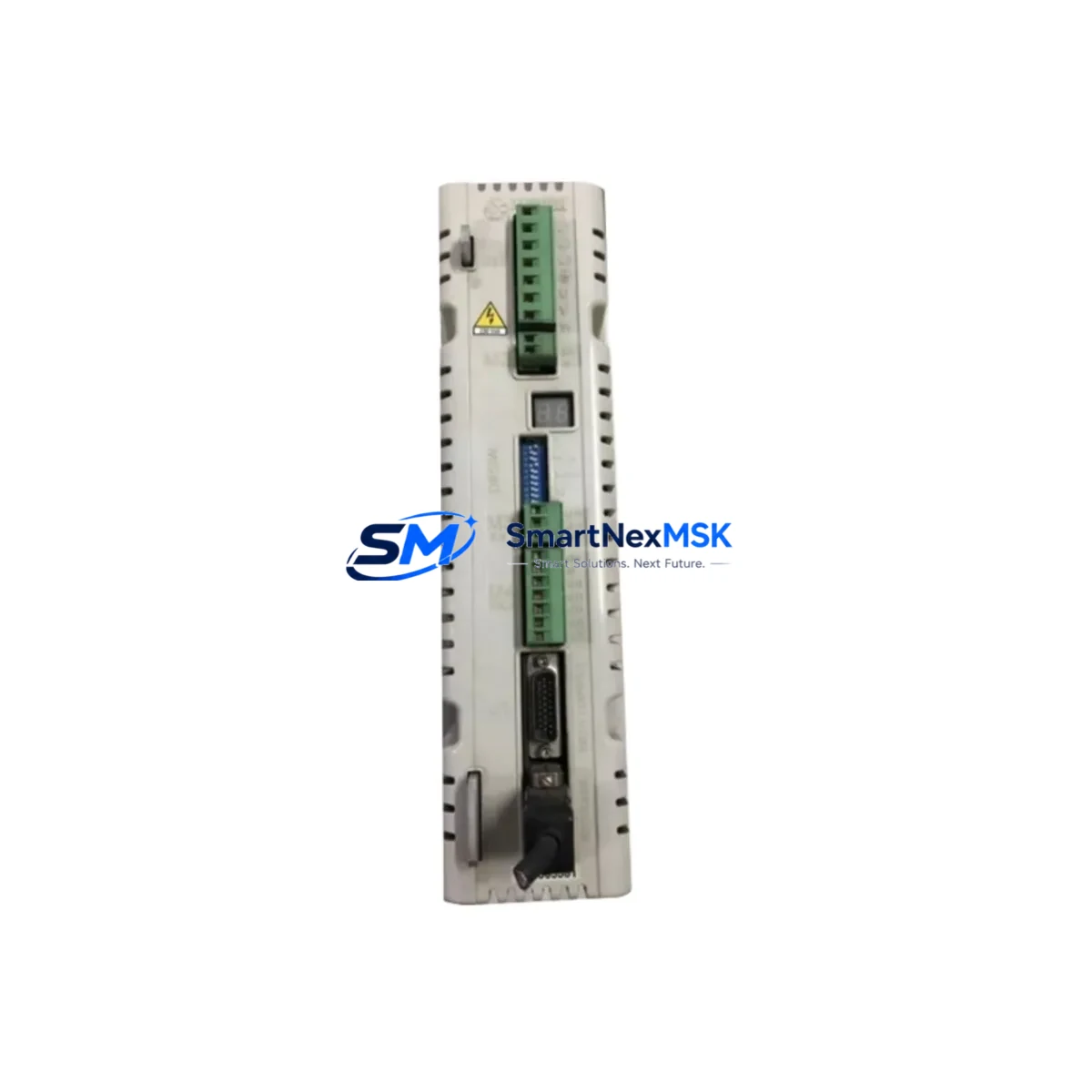
BARUFFALDI DMS-08BF Retrofit-Ready AC Servo Drive for DMS Series: Compatible Modernization & Smooth Legacy System Upgrade
The BARUFFALDI DMS-08BF is a high-performance AC servo drive engineered for seamless integration into existing DMS Series control architectures. Whether you are replacing a discontinued unit, upgrading an aging control cabinet, or migrating a legacy automation line to a more reliable platform, the DMS-08BF delivers the electrical compatibility, mechanical fit, and communication protocol support required for a confident, low-risk retrofit. With verified stock availability, factory-tested units, and a 12-month warranty, this drive is the preferred choice for maintenance engineers and system integrators managing long-running industrial assets.
Upgrade Compatibility Table
| Parameter | Details |
|---|---|
| Compatible Series | BARUFFALDI DMS Series (DMS-04BF, DMS-06BF, DMS-08BF, DMS-12BF) |
| Drive Type | AC Servo Drive |
| Mounting Interface | Standard DIN rail / panel mount — matches original DMS Series footprint |
| Power Supply Compatibility | Verify existing cabinet power capacity before installation; confirm input voltage range matches site supply |
| Terminal Wiring | Terminal block layout consistent with DMS Series; verify encoder feedback connector pinout before wiring |
| Communication Protocol | Supports standard serial and fieldbus interfaces common to DMS Series; confirm with existing PLC or CNC controller |
| Replacement Recommendation | Direct replacement for discontinued DMS-08BF units; cross-reference with DMS-06BF and DMS-12BF for adjacent capacity needs |
| Commissioning Notes | Re-upload original parameter set; verify axis tuning, torque limits, and speed references after installation |
| Warranty | 12-Month Warranty — covers manufacturing defects and functional failure under normal operating conditions |
| Origin | Italy (BARUFFALDI) |
Retrofit Planning for Existing Automation Systems
A successful DMS-08BF retrofit begins well before the drive arrives on site. The first step is a thorough audit of the existing control cabinet: document the current power supply rail capacity, confirm that the 24 VDC logic supply and the main AC input voltage are within the DMS-08BF’s rated input range, and verify that the existing circuit breakers and fuses are correctly sized for the new unit’s inrush and continuous current draw.
Terminal wiring is the next critical checkpoint. The DMS Series uses a defined terminal block layout for power input, motor output (U/V/W), brake resistor, and control signals. Before disconnecting the old drive, photograph and label every wire, and cross-reference the terminal assignments against the DMS-08BF wiring diagram. Pay particular attention to the encoder feedback cable: the DMS-08BF uses a specific connector type for the resolver or incremental encoder interface, and any mismatch here will prevent the drive from achieving closed-loop position control.
In multi-axis systems, the DMS-08BF typically shares a common DC bus or backplane with adjacent drives. If your installation includes a DMS-04BF or DMS-06BF on the same rack, confirm that the shared bus voltage and regenerative braking capacity remain within specification after the swap. The system’s servo controller or CNC unit — which may be a dedicated motion controller, a PLC with motion modules, or an integrated CNC platform — must be able to recognize the DMS-08BF’s axis address and parameter set. Before powering up, reload the original parameter file from your backup, or re-enter the axis configuration manually if no backup exists.
Communication link integrity is equally important. The DMS Series drives communicate with the host controller via serial interfaces or fieldbus protocols. After physical installation, verify that the communication cable — whether RS-232, RS-485, or a proprietary fieldbus link — is correctly terminated and that the drive’s node address matches the original configuration. If the host system includes an HMI panel, confirm that the HMI screen addresses and variable mappings still correspond to the correct axis after the drive replacement. In systems where the HMI reads drive status registers directly, a firmware or parameter mismatch can cause alarm displays or incorrect status reporting.
For I/O-intensive applications, check that all digital inputs and outputs — including enable signals, fault resets, speed references, and position feedback — are correctly mapped and that signal levels (NPN/PNP, 24 VDC/5 VDC) are compatible. If the original installation used a dedicated programming cable or USB-to-serial adapter for drive configuration, ensure the same interface is available for the DMS-08BF commissioning session. Some retrofit projects also require updating the host PLC program to accommodate minor differences in fault codes or status word bit assignments between drive generations.
Finally, before returning the machine to production, conduct a full functional test: jog each axis through its travel range, verify position accuracy against a known reference, confirm that the brake engages and releases correctly, and check that all safety interlocks — including emergency stop, overtravel limits, and drive fault outputs — operate as expected. Document the final parameter set and store a backup copy off-site.
Downtime Control During System Migration
Minimizing unplanned downtime during a servo drive replacement requires preparation, not improvisation. The most effective strategy is to pre-stage the DMS-08BF before the maintenance window opens: unbox and inspect the unit, verify the firmware version, and load the parameter backup from the outgoing drive. If the original parameter file is unavailable, reconstruct the key settings — motor rated current, encoder resolution, speed and torque limits, acceleration ramps, and communication node address — from the machine’s maintenance records or the original commissioning report.
During the swap, work systematically: isolate the cabinet, discharge the DC bus, remove the old drive, install the DMS-08BF, reconnect all terminals in the documented sequence, and restore power in stages — logic supply first, then main power. This staged power-up approach allows you to verify communication link integrity and parameter recognition before the motor is energized, reducing the risk of a fault trip that extends the outage.
If the machine runs a continuous process where even a brief interruption is costly, consider preparing a spare axis by pre-configuring a second DMS-08BF unit with the correct parameter set. This hot-spare approach reduces the actual swap time to the physical installation and wiring reconnection, typically achievable within a single shift. Once the replacement drive is running, monitor the axis for the first production cycle to confirm that position accuracy, cycle time, and thermal performance match the original specification before signing off on the retrofit.
All DMS-08BF units supplied by SMARTNEXMSK are tested prior to shipment and covered by a 12-month warranty. In-stock units are available for same-week dispatch, supporting urgent replacement scenarios where production continuity is the priority.
Retrofit Support FAQ
Q1: Is the DMS-08BF a direct drop-in replacement for my existing BARUFFALDI DMS Series drive?
The DMS-08BF is designed as a compatible replacement within the DMS Series family. Mechanical mounting dimensions, terminal block layout, and communication interface are consistent with the series standard. However, always verify the power rating, encoder interface type, and firmware version against your specific machine documentation before installation, as minor hardware revisions may exist across production batches.
Q2: What do I need to check before wiring the DMS-08BF into my existing cabinet?
Confirm input voltage range, phase configuration, and supply capacity. Verify terminal assignments for motor output (U/V/W), encoder feedback connector pinout, brake resistor connection, and all control signal I/O. Cross-reference the DMS-08BF wiring diagram against your existing cabinet drawings before making any connections.
Q3: How do I restore my original axis parameters after installing the DMS-08BF?
If a parameter backup file exists, upload it via the drive’s serial interface using the original programming cable or a compatible USB-to-serial adapter. If no backup is available, re-enter the key parameters manually: motor rated current, encoder resolution, speed and torque limits, acceleration/deceleration ramps, and communication node address. After parameter restore, perform a full functional test before returning the axis to automatic operation.
Q4: What does the 12-month warranty cover, and how is it handled?
The 12-month warranty covers manufacturing defects and functional failure under normal operating conditions. Units that develop a fault within the warranty period are eligible for replacement or repair. Contact SMARTNEXMSK at sales@smartnexmsk.com or +86 18259474341 to initiate a warranty claim. All units are tested prior to shipment to minimize the risk of DOA (dead-on-arrival) failures.
© 2026 SMARTNEXMSK. All rights reserved.
Original Source: https://smartnexmsk.com
Contact: sales@smartnexmsk.com | +86 18259474341