BERKELEY BXI4/2-01-B Spare for BXI Series Automation: Spare Replacement & Downtime Risk Control
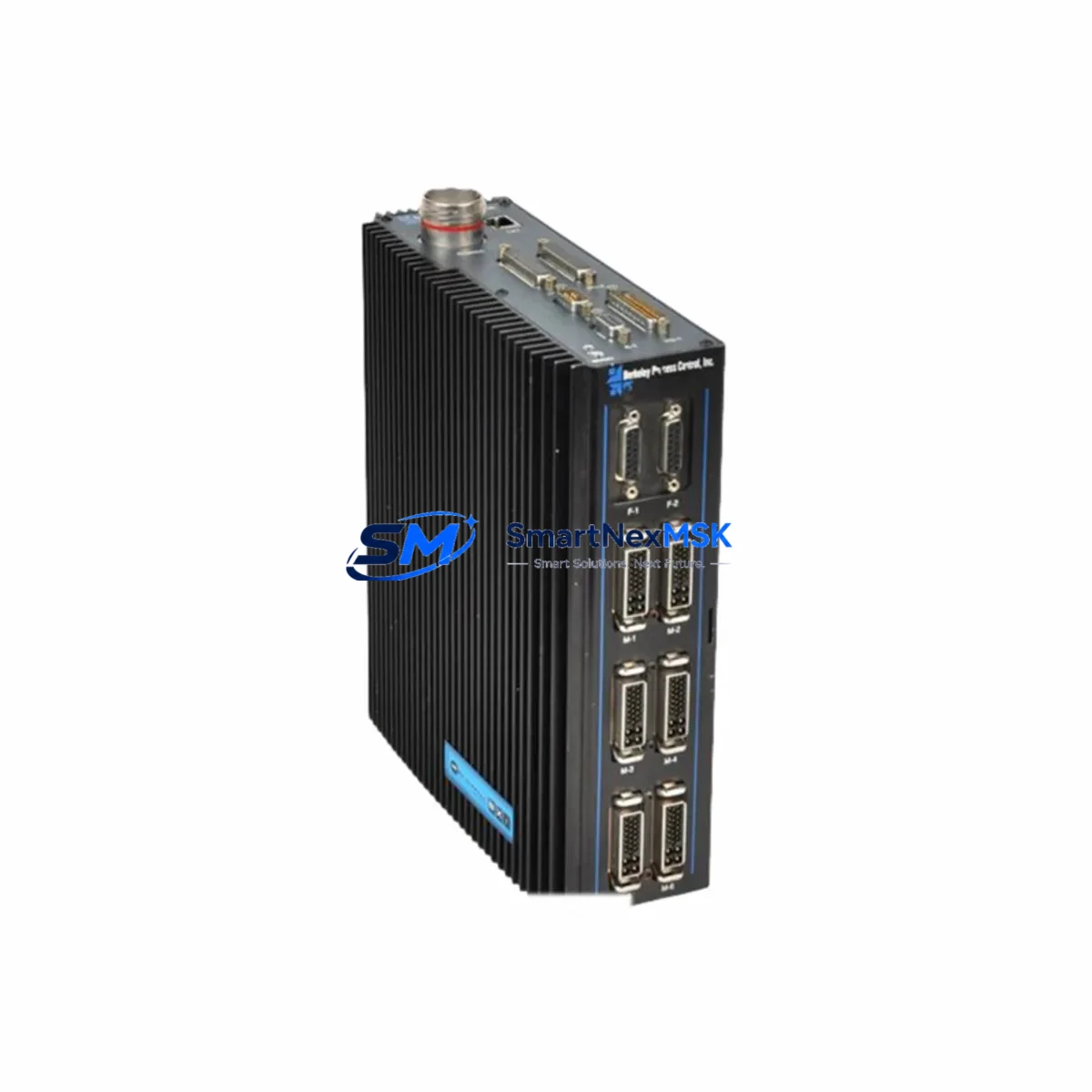
The BERKELEY BXI4/2-01-B is a 4-axis motion controller belonging to the BXI Series, engineered for precision industrial automation applications including CNC machining centers, multi-axis servo coordination, and high-throughput production lines. When this controller fails or reaches end-of-service life, unplanned downtime can cascade across an entire production cell. Sourcing a verified, original-specification spare unit is the fastest path to restoring system operation without compromising axis synchronization, encoder feedback integrity, or PLC communication handshake protocols.
At SMARTNEXMSK, every BXI4/2-01-B unit is sourced from authorized supply chains, subjected to pre-shipment functional verification, and dispatched with full traceability documentation. Our inventory is maintained specifically to support maintenance engineers and procurement teams who cannot afford extended lead times on critical motion control components.
Spare Maintenance Table
| Parameter | Specification / Detail |
|---|---|
| Part Number / SKU | BXI4/2-01-B |
| Brand | BERKELEY |
| Series | BXI Series |
| Product Type | 4-Axis Motion Controller |
| Axis Count | 4 axes (coordinated motion) |
| Origin | Germany (DE) |
| Compatibility | BXI Series motion control systems; compatible with standard servo drives, encoder feedback modules, and industrial fieldbus networks |
| Installation | DIN rail or panel mount; refer to BXI Series mechanical drawing for slot and connector alignment |
| Operating Environment | Industrial control cabinet; standard IEC 60068 environmental ratings apply |
| Communication Interface | Fieldbus-ready (EtherCAT / PROFIBUS / CANopen depending on firmware variant) |
| Maintenance Recommendation | Inspect encoder cable shielding, servo drive enable signals, and 24 VDC logic supply before replacement |
| Warranty | 12 Months — covers manufacturing defects and functional failure under normal operating conditions |
| Pre-Shipment Test | Functional power-on and communication handshake verification performed before dispatch |
| Lead Time | In-stock units ship within 1–3 business days |
Maintenance Planning for Continuous Operation
Replacing the BXI4/2-01-B in a live production environment requires more than swapping the controller. A disciplined maintenance engineer will treat this replacement as an opportunity to audit the entire motion control loop and adjacent electrical infrastructure. Before powering down the cabinet, verify that the 24 VDC logic power supply — typically a BERKELEY or equivalent branded PSU module — is delivering stable voltage within tolerance, as an under-voltage condition is a common root cause of controller faults that are misdiagnosed as controller hardware failure.
Once the cabinet is de-energized, inspect the servo drive units connected to each of the four axes. BERKELEY BXI Series servo drives share the same backplane communication bus as the BXI4/2-01-B, and a degraded drive can corrupt axis data even after a controller replacement. Check the encoder feedback cables for each axis — shielding continuity and connector seating are frequent failure points in high-vibration environments. If the system uses a BERKELEY BXI Series I/O expansion module for digital inputs and outputs, verify that the I/O module firmware version is compatible with the replacement controller’s firmware revision.
For systems integrated with a PROFIBUS or EtherCAT network, inspect the communication module or gateway card installed in the same rack. A faulty fieldbus node can prevent the new BXI4/2-01-B from establishing a master-slave handshake, causing a startup fault that appears to be a controller defect. Similarly, check the terminal blocks and wiring harnesses on the I/O side — loose terminations on analog reference signals or digital enable lines are a leading cause of intermittent axis faults.
If the control cabinet includes a signal isolator or galvanic isolation barrier between the controller and field devices, verify isolation resistance before recommissioning. Relay output modules used for spindle enable, brake release, or safety interlock functions should also be inspected for contact wear, particularly if the system has accumulated high cycle counts. Fuse holders and miniature circuit breakers protecting the 24 VDC and 48 VDC rails should be checked for thermal discoloration, which indicates sustained overcurrent events that may have stressed the original controller.
For facilities managing aging BXI Series installations, maintaining a minimum spare inventory of one BXI4/2-01-B controller alongside matched servo drive modules and a spare HMI operator panel significantly reduces mean time to repair (MTTR). Procurement engineers should also consider stocking a spare backplane connector set and a replacement battery for SRAM parameter retention, as these consumable components are often overlooked until a critical failure occurs.
Site Replacement Workflow
Step 1 — Parameter Backup: Before removing the existing BXI4/2-01-B, use the BERKELEY programming software to export all axis parameters, cam profiles, and motion programs to a USB drive or engineering workstation. Confirm the backup file integrity before proceeding.
Step 2 — Cabinet De-energization: Isolate the main power supply and verify zero-energy state using a calibrated voltage tester. Lock out / tag out (LOTO) per site safety procedures.
Step 3 — Controller Removal: Disconnect all fieldbus cables, encoder connectors, and I/O wiring harnesses in sequence. Label each connector if not already marked. Remove the controller from the DIN rail or panel mount.
Step 4 — Inspection Window: With the controller removed, inspect the backplane connectors, adjacent servo drive status LEDs (if battery-backed), and the condition of the cable management tray. Replace any damaged cable ties or ferrite cores.
Step 5 — Replacement Installation: Mount the new BXI4/2-01-B, reconnect all cables in reverse order, and verify connector seating. Restore power to the 24 VDC logic rail first and confirm the controller powers on without fault codes.
Step 6 — Parameter Restore & Commissioning: Load the backed-up parameter file, perform a low-speed axis jog test on all four axes, and verify encoder feedback counts match expected values. Gradually restore full production speed and monitor for thermal or communication anomalies during the first operating shift.
This workflow minimizes downtime, preserves system compatibility, and ensures the replacement controller is fully validated before returning the machine to production.
Spare Parts Support FAQ
Q1: Is the BXI4/2-01-B a direct drop-in replacement for the original unit?
Yes. Each unit supplied by SMARTNEXMSK is sourced to original BERKELEY specifications and is a direct functional replacement for the BXI4/2-01-B. No hardware modification is required. Parameter files from the original unit can be restored directly to the replacement controller using standard BERKELEY commissioning software.
Q2: What pre-shipment testing is performed on each unit?
Every BXI4/2-01-B undergoes a functional power-on test and communication interface verification before dispatch. Units that fail any test parameter are quarantined and not shipped. A test report is available upon request for quality-critical procurement processes.
Q3: How should I manage BXI4/2-01-B spare inventory for a multi-machine facility?
For facilities operating three or more BXI Series machines, we recommend maintaining at least one BXI4/2-01-B in on-site stock at all times. Given the controller’s role as the central motion coordination node, a single unit failure can idle an entire production cell. Long-term supply agreements with SMARTNEXMSK can lock in pricing and ensure priority allocation during periods of market shortage.
Q4: What is covered under the 12-month warranty?
The 12-month warranty covers manufacturing defects and functional failure under normal operating conditions as defined by BERKELEY’s published environmental and electrical specifications. Warranty claims are supported by SMARTNEXMSK’s technical team, with replacement or repair options available. The warranty period begins from the date of confirmed delivery.
© 2026 SMARTNEXMSK. All rights reserved.
Original Source: https://smartnexmsk.com
Contact: sales@smartnexmsk.com | +86 18259474341