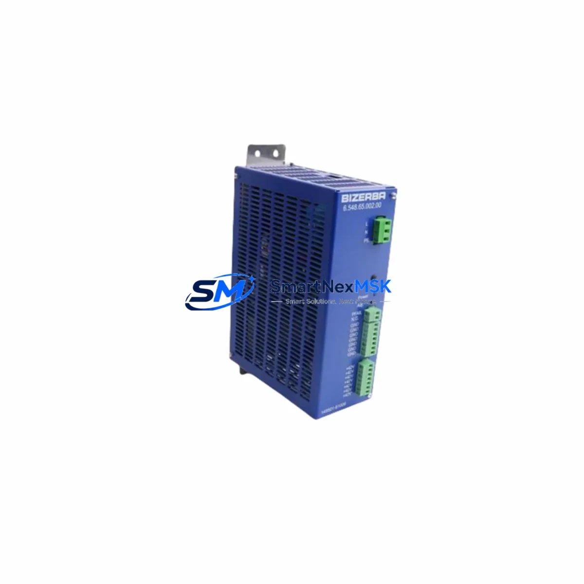
BIZERBA 6.548.65.002.00 Retrofit-Ready Power Supply for SE/BI Series Control Systems
The BIZERBA 6.548.65.002.00 is a retrofit-ready printer power supply module engineered for seamless integration into BIZERBA SE and BI series label printing and weighing systems. As legacy BIZERBA control platforms approach end-of-life and original spare parts become increasingly scarce, this module serves as a verified drop-in replacement that restores full system functionality without requiring firmware changes, panel rewiring, or PLC program modification. Whether you are managing a planned upgrade cycle or responding to an unplanned failure on the production floor, the 6.548.65.002.00 is stocked and ready for immediate dispatch.
Industrial facilities running BIZERBA SE-series or BI-series integrated weighing and labelling lines frequently encounter power supply degradation as the primary failure mode after years of continuous operation. The 6.548.65.002.00 addresses this directly: it matches the original output voltage rails, connector pinout, and mounting footprint of the factory-installed unit, eliminating the need for custom cable adapters or bracket modifications during installation. Technicians familiar with BIZERBA control cabinet layouts will find the swap procedure straightforward, typically completable within a single maintenance window.
Upgrade Compatibility Table
| Parameter | Details |
|---|---|
| SKU / Part Number | 6.548.65.002.00 |
| Compatible Series | BIZERBA SE Series, BIZERBA BI Series |
| Module Function | Printer Power Supply |
| Mounting Interface | Direct drop-in; matches OEM footprint and connector layout |
| Communication Compatibility | Compatible with existing BIZERBA system bus and printer interface boards |
| Replacement Recommendation | Verified replacement for end-of-life and discontinued OEM units |
| Commissioning Notes | No firmware update required; verify output voltage rails before power-on |
| Warranty | 12 Months from date of shipment |
| Origin | Germany (DE) |
| Weight | 1,640 g |
Retrofit Planning for Existing Automation Systems
A successful retrofit of the BIZERBA 6.548.65.002.00 begins well before the module arrives on site. Engineers should first audit the control cabinet to confirm the existing power distribution architecture. In SE-series installations, the printer power supply typically shares a 24 VDC bus with the main weighing controller board and the label feed motor driver. Before removal, document all terminal block assignments on the outgoing unit — particularly the DC output terminals feeding the print head driver board and the AC input terminals connected to the cabinet’s primary circuit breaker rail.
In systems where the BIZERBA SE controller interfaces with a Siemens S7-300 or S7-400 PLC via PROFIBUS-DP, the power supply replacement does not affect the fieldbus communication layer directly, but a controlled power-down sequence is essential to avoid corrupting the DP master’s device table. Similarly, installations using a BIZERBA CWP or GLM-I interface module for checkweigher integration should follow the manufacturer’s shutdown procedure to preserve calibration data stored in the interface module’s non-volatile memory.
For lines where the BIZERBA printer is networked via Ethernet TCP/IP to a plant-level MES or ERP system, the IP address and subnet configuration stored in the printer’s network interface card are unaffected by a power supply swap, provided the replacement is performed with the network cable disconnected and reconnected only after the new module has stabilised at operating temperature. Technicians should also verify that the BIZERBA PC software — typically running on a dedicated industrial PC connected via RS-232 or USB — retains its COM port assignment after the cabinet is re-energised.
In older BI-series installations that include a BIZERBA K-class or M-class scale head connected to the printer via a serial data cable, the retrofit window is an ideal opportunity to inspect the serial interface board and the ribbon cable connecting the print head assembly to the main logic board. Replacing the power supply while these ancillary components are accessible reduces the risk of a secondary failure shortly after the primary repair. If the installation also includes a BIZERBA label rewinder module or an external label applicator driven by a 24 VDC signal from the power supply, confirm that the output current capacity of the 6.548.65.002.00 is sufficient to drive all connected loads simultaneously before closing the cabinet.
Sites operating mixed fleets — for example, a combination of BIZERBA SE-series printers alongside newer BIZERBA GLM-Ievo or BIZERBA BW-series checkweighers — should maintain a documented spare parts register that includes the 6.548.65.002.00 alongside other high-wear consumables such as the print head module, the platen roller assembly, and the label sensor board. Proactive stocking of these components significantly reduces mean time to repair (MTTR) and supports compliance with food safety and pharmaceutical GMP audit requirements that mandate documented equipment maintenance records.
Downtime Control During System Migration
Minimising production downtime during a BIZERBA power supply replacement requires a structured pre-outage preparation protocol. Before scheduling the maintenance window, verify that a tested and bench-checked 6.548.65.002.00 unit is physically on hand — do not initiate the cabinet shutdown until the replacement module has been inspected and confirmed functional. Where possible, perform a bench power-on test using a variable DC load to verify that all output rails are within specification before the unit enters the production environment.
During the outage, the highest risk to production continuity is not the physical swap itself but the re-commissioning sequence. Technicians should follow a fixed checklist: (1) isolate AC mains to the cabinet; (2) discharge any capacitor banks in the existing power supply; (3) photograph all terminal connections before disconnection; (4) install the 6.548.65.002.00 and reconnect terminals in reverse order of removal; (5) perform a controlled power-on with the print head drive circuit isolated; (6) verify DC output voltages at the terminal block before reconnecting the print head; (7) run a test label print cycle and confirm data integrity against the MES print job queue.
For facilities where the BIZERBA printer is part of a continuous packaging line, coordinate the maintenance window with the upstream PLC — typically a Siemens S7 or Allen-Bradley ControlLogix controller managing the conveyor and reject system — to ensure that the line hold signal is active and that no product is queued at the labelling station during the swap. This prevents label misapplication events that could trigger downstream quality holds. After the replacement is complete and the system has returned to normal operation, log the intervention in the equipment maintenance record and update the spare parts register to reflect the reduced on-hand stock of the 6.548.65.002.00.
Retrofit Support FAQ
Q1: Is the BIZERBA 6.548.65.002.00 a direct replacement for the original factory-installed unit in SE and BI series printers?
Yes. The 6.548.65.002.00 is a verified drop-in replacement that matches the OEM connector pinout, output voltage specification, and mechanical mounting footprint. No wiring adapters or bracket modifications are required for standard SE-series and BI-series cabinet configurations.
Q2: Does replacing the power supply require any changes to the BIZERBA printer firmware or PLC program?
No firmware update or PLC program modification is required. The power supply is a passive power conversion component; it does not store configuration data or communicate with the control system beyond providing regulated DC voltage to the downstream boards. Existing label formats, print parameters, and network settings are preserved.
Q3: What commissioning checks should be performed after installing the 6.548.65.002.00?
After installation, verify DC output voltage at the terminal block before reconnecting the print head drive circuit. Run a test print cycle and confirm label registration, print quality, and data accuracy against a known reference job. If the printer is networked, confirm that the IP address and MES communication link are restored. Document the commissioning result in the equipment maintenance log.
Q4: What warranty coverage is provided, and what does it include?
The 6.548.65.002.00 is covered by a 12-month warranty from the date of shipment. The warranty covers manufacturing defects and component failures under normal operating conditions. Each unit undergoes functional testing prior to dispatch. For warranty claims or technical support, contact the sales team with the order reference and a description of the observed fault.
© 2026 SMARTNEXMSK. All rights reserved.
Original Source: https://smartnexmsk.com
Contact: sales@smartnexmsk.com | +86 18259474341