BODINE 33A5FEPM-3W Retrofit-Ready DC Gearmotor: Seamless Compatibility for FPM Series Modernization
The BODINE 33A5FEPM-3W is a 90VDC DC permanent magnet gearmotor engineered for direct retrofit into legacy FPM Series drive systems. As industrial facilities face increasing pressure to modernize aging motion control infrastructure — whether driven by discontinued spare parts, obsolete drive controllers, or tightening energy efficiency mandates — the 33A5FEPM-3W delivers a validated drop-in upgrade path that minimizes engineering risk and eliminates costly line reconfigurations.
Designed with a 33:1 gear ratio and compact NEMA-frame footprint, this unit is purpose-built for applications where the original BODINE FPM-frame gearmotors have reached end-of-life or where procurement lead times on legacy units have become operationally unacceptable. Whether you are replacing a failed unit on a packaging conveyor, upgrading a legacy web-tension control system, or retrofitting a multi-axis positioning table, the 33A5FEPM-3W provides the mechanical and electrical compatibility required for a controlled, low-risk changeover.
Procurement teams and maintenance engineers sourcing this unit should verify the following before installation: confirm the existing drive controller — such as a BODINE WPM Series DC drive or a compatible third-party SCR drive — is rated for 90VDC armature voltage and can supply adequate continuous current for the replacement motor’s rated load. Check the existing terminal block wiring for A1/A2 armature leads and F1/F2 field leads if applicable, and confirm that the motor’s shaft diameter, keyway dimensions, and mounting bolt pattern match the original FPM-frame specification. If the system uses a BODINE Type FPM tachometer feedback assembly, verify encoder or tach signal compatibility with the upstream controller before energizing.
Upgrade Compatibility Table
| Parameter | Detail |
|---|---|
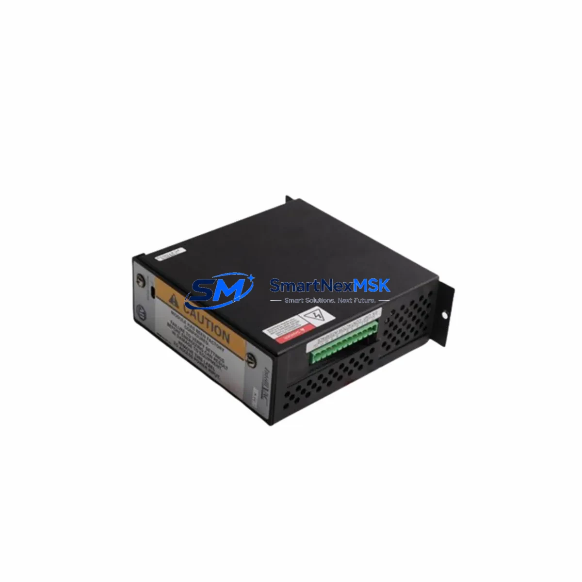
| SKU / Model | 33A5FEPM-3W |
| Brand | BODINE Electric Company |
| Series | FPM (Permanent Magnet DC Gearmotor) |
| Voltage | 90VDC Armature |
| Gear Ratio | 33:1 |
| Frame / Mounting | NEMA FPM-frame, face-mount compatible |
| Shaft Interface | Keyed output shaft — verify OD and keyway before installation |
| Terminal / Wiring | A1/A2 armature terminals; confirm lead gauge matches existing harness |
| Drive Compatibility | BODINE WPM DC Drive, SCR-type 90VDC drives, regenerative drives |
| Feedback / Encoder | Confirm tach/encoder compatibility if closed-loop speed control is used |
| Communication | Analog speed reference (0–10VDC or 4–20mA via upstream drive) |
| Replacement Suitability | Direct retrofit for discontinued FPM-frame units; verify nameplate specs |
| Commissioning Note | Perform no-load run test before coupling to driven load |
| Warranty | 12 Months from date of shipment |
| Origin | United States |
Retrofit Planning for Existing Automation Systems
A successful retrofit of the BODINE 33A5FEPM-3W into an existing production line requires a structured pre-installation audit. Begin by documenting the full drive train: identify the upstream DC drive controller (e.g., a BODINE WPM-100 or WPM-200 SCR drive), the existing motor nameplate data, and the mechanical coupling arrangement. If the system is part of a multi-axis coordinated motion platform, note the master/follower speed reference architecture before disconnecting any wiring.
For systems that include a BODINE Type FPM encoder or tachometer feedback module, the feedback signal chain must be validated independently. Tachometer output voltage at rated speed should be measured and compared against the drive’s feedback input specification. If the legacy tach is integrated into the motor end-bell, confirm whether the 33A5FEPM-3W is ordered with or without the feedback option, and plan accordingly for a separate incremental encoder retrofit kit if closed-loop speed regulation is required.
Control cabinet integration is the next critical checkpoint. Verify that the existing motor starter contactor, overload relay, and fusing are appropriately rated for the replacement motor’s FLA (full-load amperage). If the original installation used a BODINE regenerative braking resistor or dynamic braking module, confirm that the braking circuit remains compatible with the replacement unit’s back-EMF characteristics. For systems with a BODINE Type WPM or equivalent DC drive, the IR compensation and current limit potentiometers may require re-trimming after motor swap to optimize speed regulation under load.
In multi-motor conveyor or web-handling systems, also account for the BODINE parallel shaft gearbox or right-angle worm gear reducer that may be coupled downstream. Gear reducer input torque ratings and service factors should be re-confirmed against the replacement motor’s stall torque to prevent premature gearbox wear. Where the original system used a BODINE Type FPM-3 or FPM-5 frame motor with a specific overhung load rating, verify that the replacement unit’s bearing specification meets or exceeds the original.
Finally, if the system interfaces with a PLC-based supervisory controller — such as an Allen-Bradley MicroLogix or Siemens S7-1200 — through the DC drive’s analog speed reference input, confirm that the PLC analog output module’s signal range (0–10VDC or 4–20mA) is correctly scaled in the drive parameters before commissioning. No program changes to the PLC ladder logic should be required for a like-for-like motor replacement, but speed reference scaling and acceleration/deceleration ramp times should be verified during the initial no-load test run.
Downtime Control During System Migration
Minimizing unplanned downtime during a gearmotor retrofit is a function of preparation, not speed. For the BODINE 33A5FEPM-3W replacement, the recommended approach is to pre-stage the replacement unit fully before the maintenance window opens: pre-wire the motor leads to a terminal strip, pre-mount any required encoder or tach assembly, and pre-confirm shaft and coupling dimensions against the driven equipment.
During the changeover window, follow a structured sequence: de-energize and lock out the drive system per LOTO procedures, disconnect the existing motor leads at the drive terminal block (photograph the wiring before removal), unbolt the motor from its mounting, and install the replacement unit. Reconnect leads in the same terminal positions, restore power, and perform a no-load run at reduced speed reference (approximately 25–30% of rated speed) before coupling to the load. Monitor motor temperature, current draw, and speed stability during the initial loaded run.
To protect existing program logic, no modifications to the upstream PLC program should be necessary for a direct motor replacement. If the system uses a BODINE WPM drive with preset speed references stored in potentiometer settings rather than digital parameters, document all pot positions before the swap and restore them after installation. For systems with HMI speed displays calibrated to the original motor’s tach output, verify that the displayed speed matches the actual shaft RPM after commissioning — recalibrate the HMI scaling if a different feedback device is installed. Keeping the changeover window to under four hours is achievable with proper pre-staging, and the 12-month warranty on the replacement unit provides operational assurance through the first full production cycle post-retrofit.
Retrofit Support FAQ
Q1: Is the BODINE 33A5FEPM-3W a direct drop-in replacement for all FPM-frame gearmotors?
The 33A5FEPM-3W is dimensionally compatible with BODINE FPM-frame mounting configurations, but you must verify the gear ratio (33:1), output shaft diameter, keyway dimensions, and voltage rating (90VDC) against your original nameplate before installation. Units with different gear ratios or shaft configurations within the FPM family are not interchangeable without mechanical adaptation.
Q2: What commissioning steps are required after installation?
After mechanical installation and wiring reconnection, perform a no-load run at 25–30% speed reference to verify rotation direction, check for abnormal noise or vibration, and confirm current draw is within the drive’s current limit setting. Then couple to the load, ramp to full speed, and verify speed stability and temperature rise over a 30-minute loaded run. Re-trim the drive’s IR compensation if speed droop under load exceeds acceptable limits.
Q3: Will I need to modify my existing wiring or control cabinet?
For a like-for-like replacement, no wiring modifications should be required beyond reconnecting the A1/A2 armature leads at the drive terminal block. If the replacement unit has a different lead gauge or connector type than the original, use appropriately rated terminal ferrules and confirm that the existing overload relay is set to the replacement motor’s FLA rating. If a feedback device (encoder or tach) is being added or changed, additional wiring to the drive’s feedback input terminals will be required.
Q4: What does the 12-month warranty cover, and how is it processed?
The 12-month warranty covers manufacturing defects in materials and workmanship from the date of shipment. Units that fail under normal operating conditions within the warranty period are eligible for replacement or repair. To initiate a warranty claim, contact our sales team with the original order number, a description of the failure mode, and photographic documentation of the installation. Warranty does not cover damage resulting from incorrect installation, overvoltage, overload beyond rated specifications, or unauthorized modification.
© 2026 SMARTNEXMSK. All rights reserved.
Original Source: https://smartnexmsk.com
Contact: sales@smartnexmsk.com | +86 18259474341