BONITRON M3575R-H33BF Spare for M3575R Automation: Spare Replacement & Industrial Downtime Risk Control
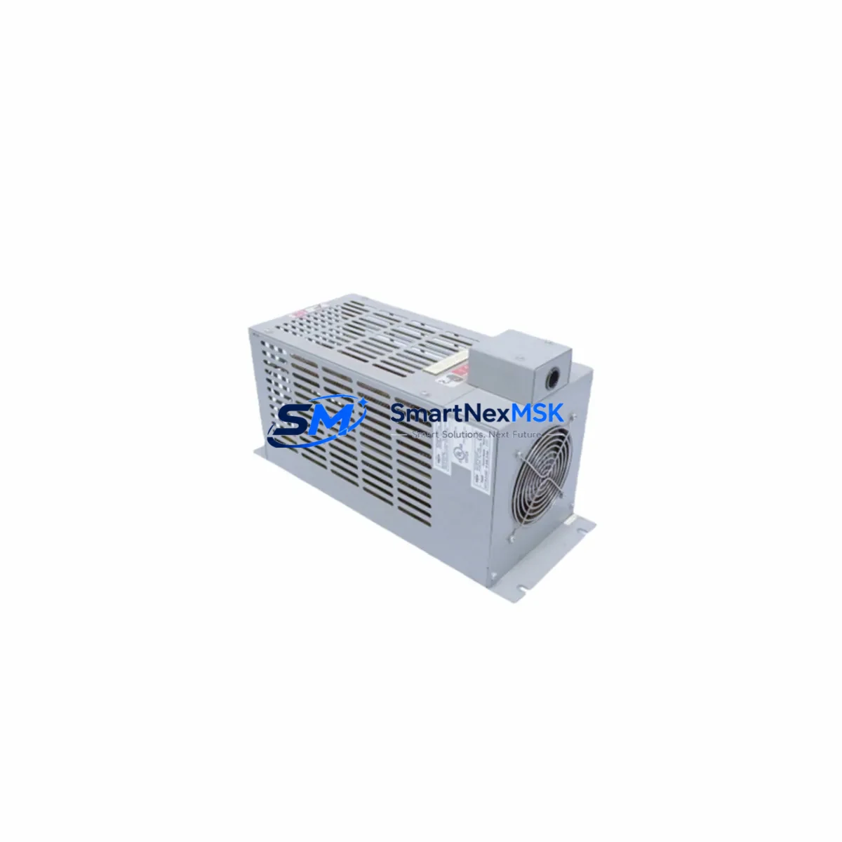
The BONITRON M3575R-H33BF is an original dynamic braking resistor engineered for the M3575R series variable frequency drive (VFD) platform. In industrial automation environments where motor deceleration control is critical — including conveyor systems, hoists, centrifuges, and high-inertia load applications — the dynamic braking resistor is a front-line component that absorbs regenerative energy during motor braking cycles. A failed or degraded M3575R-H33BF can result in DC bus overvoltage faults, drive trips, and unplanned production shutdowns. Maintaining a verified spare on the shelf is the most effective strategy for minimizing mean time to repair (MTTR) and protecting continuous operation.
For maintenance engineers managing aging VFD installations, the M3575R-H33BF represents a direct, specification-matched replacement that eliminates compatibility risk. For procurement engineers, sourcing this component from a reliable supplier with documented 12-month warranty coverage and pre-shipment testing ensures that the spare entering your storeroom is ready to install — not a source of additional troubleshooting.
Spare Maintenance Table
| Parameter | Specification / Detail |
|---|---|
| Part Number / SKU | M3575R-H33BF |
| Brand | BONITRON |
| Series | M3575R |
| Product Type | Dynamic Braking Resistor |
| Application | VFD / Variable Frequency Drive braking energy dissipation |
| Compatibility | BONITRON M3575R series VFD platforms; verify drive model and braking chopper rating before installation |
| Mounting / Installation | External resistor bank; connect to braking chopper terminals per M3575R wiring diagram |
| Operating Environment | Industrial panel / control cabinet; ensure adequate ventilation and thermal clearance |
| Country of Origin | China (CN) |
| Unit Weight | 1,850 g (approx.) |
| Maintenance Recommendation | Inspect resistance value and thermal condition at each planned maintenance interval; replace if resistance drift exceeds ±5% of rated value or thermal discoloration is observed |
| Warranty | 12 Months — covers manufacturing defects; each unit tested prior to shipment |
| Lead Time | In-stock units ship within 1–3 business days; confirm availability at order |
Maintenance Planning for Continuous Operation
When a maintenance or reliability engineer schedules replacement of the M3575R-H33BF, the braking resistor should never be treated as an isolated component. The dynamic braking circuit is part of a broader energy management loop within the VFD control cabinet, and a thorough inspection of adjacent components during the same maintenance window significantly reduces the risk of repeat failures and callback visits.
Begin with the braking chopper module internal to the M3575R drive — if the resistor has failed due to sustained overload, the chopper IGBT may have sustained thermal stress and should be evaluated. Inspect the DC bus capacitor bank for bulging, leakage, or elevated ESR, as capacitor degradation is a common root cause of recurring overvoltage faults that accelerate resistor wear. Check the input line reactor or AC choke for signs of overheating or insulation breakdown, particularly in installations with poor power quality.
On the control side, verify the 24 VDC control power supply output voltage and ripple — an unstable control supply can cause erratic braking command signals that result in resistor thermal cycling beyond design limits. Inspect all terminal blocks and power wiring connections at the braking resistor terminals and drive output terminals; loose connections generate localized heating that degrades both the resistor and the cable insulation over time. If the installation includes a contactor or relay in the braking circuit for safety isolation, check contact condition and coil resistance.
For drives integrated into a networked control architecture, confirm that the communications module (PROFIBUS, DeviceNet, EtherNet/IP, or Modbus RTU adapter) is seated correctly and that the drive’s fault history has been reviewed for any communication-related parameter changes that may have altered braking ramp profiles. Where signal isolators are used between the PLC analog output and the drive frequency reference input, verify isolation integrity and zero/span calibration — a drifted reference signal can cause unintended deceleration rates that stress the braking resistor.
Finally, if the control cabinet houses an HMI panel for local operator control, confirm that the braking deceleration time parameter displayed and editable at the HMI matches the value stored in the drive — parameter mismatches after a drive replacement or firmware update are a common source of unexpected braking resistor overload events.
Site Replacement Workflow
Step 1 — Isolation and lockout: De-energize the VFD and apply LOTO (Lockout/Tagout) per site safety procedures. Allow the DC bus to fully discharge (verify with a calibrated meter at the DC bus terminals) before opening the braking resistor circuit.
Step 2 — Document existing configuration: Record the drive parameter set, including braking deceleration time (P-xx), braking duty cycle limit, and overvoltage stall level. Photograph the existing wiring before disconnection.
Step 3 — Remove and inspect the failed unit: Disconnect the M3575R-H33BF from the braking chopper terminals. Measure the resistance value of the removed unit and compare against the rated value — this confirms whether the failure was resistive element open-circuit, short-circuit, or thermal degradation. Retain this data for your maintenance log.
Step 4 — Install the replacement M3575R-H33BF: Connect the new unit to the braking chopper terminals using the original wiring diagram. Torque all terminal connections to specification. Verify that the resistor mounting allows adequate airflow and that no combustible materials are within the thermal exclusion zone.
Step 5 — Functional verification: Re-energize the drive and perform a controlled deceleration test at reduced load. Monitor the DC bus voltage during braking to confirm the resistor is absorbing regenerative energy correctly and that no overvoltage fault is triggered. Log the test result and return the system to service.
This workflow is applicable to both emergency replacement scenarios — where minimizing downtime is the primary objective — and planned maintenance windows where a proactive swap is being performed based on component age or condition monitoring data.
Spare Parts Support FAQ
Q1: How do I confirm the M3575R-H33BF is the correct replacement for my installation?
Verify the part number against the label on the existing resistor and cross-reference with the BONITRON M3575R drive documentation or the original panel BOM. Key parameters to match are resistance value (Ω), continuous power rating (W), and peak power rating. If the original label is illegible, contact our technical team with the drive model number and we will confirm compatibility.
Q2: What does the 12-month warranty cover, and how is it validated?
The 12-month warranty covers manufacturing defects in materials and workmanship from the date of shipment. Each M3575R-H33BF unit undergoes pre-shipment electrical testing — resistance value verification and insulation resistance check — and ships with a test record. Warranty claims require the original invoice and a description of the failure mode; field-damaged units or units showing evidence of installation error are not covered.
Q3: What is the recommended spare parts stocking strategy for the M3575R-H33BF?
For critical production lines with a single M3575R drive, maintain a minimum of one M3575R-H33BF on the shelf with a maximum shelf life of 5 years in a dry, temperature-controlled environment. For multi-drive installations or lines where downtime cost exceeds USD 5,000/hour, a 2:1 spare ratio (two spares per five installed units) is a common industry benchmark. Review and rotate stock annually.
Q4: Can the M3575R-H33BF be used as a long-term replacement for discontinued or obsolete braking resistor models?
Yes — provided the electrical specifications (resistance, power rating, and terminal configuration) are compatible with the target drive’s braking chopper requirements. BONITRON M3575R series components are designed for long-term availability to support legacy system life extension programs. Contact our sales team for cross-reference assistance if you are replacing a component from a different manufacturer or an earlier BONITRON series.
© 2026 SMARTNEXMSK. All rights reserved.
Original Source: https://smartnexmsk.com
Contact: sales@smartnexmsk.com | +86 18259474341