BRAD TCDEI-8D0P-DYU-G02: Retrofit-Ready DeviceNet Digital Input Module for Legacy Control System Upgrades
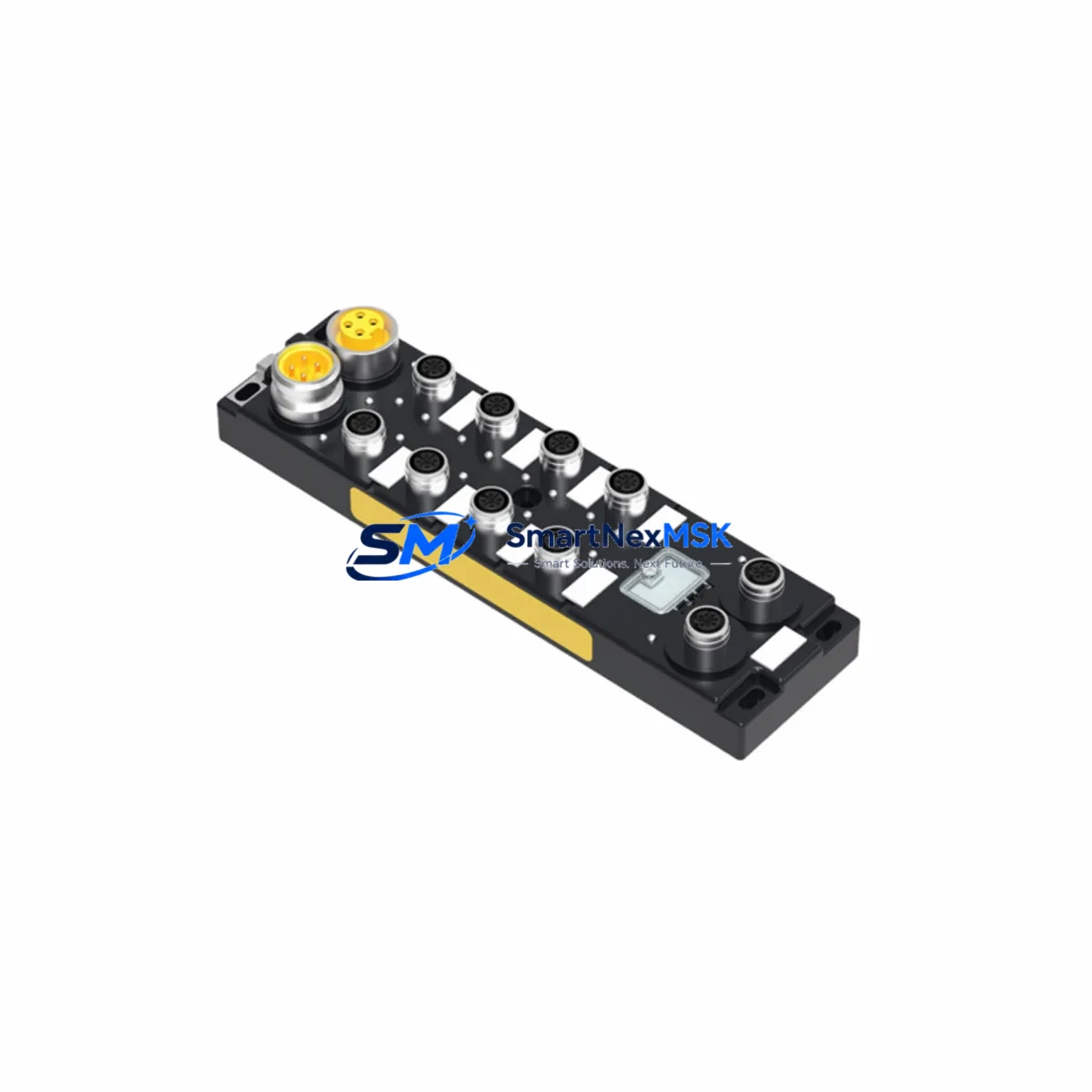
The BRAD TCDEI-8D0P-DYU-G02 is an IP67-rated, 8-channel digital input module designed for DeviceNet fieldbus networks. Built to withstand harsh industrial environments, this module serves as a direct retrofit replacement for discontinued or aging distributed I/O nodes in legacy automation systems. Whether you are modernizing a production line, recovering from a failed node, or migrating from an older DeviceNet architecture, the TCDEI-8D0P-DYU-G02 delivers reliable signal acquisition with minimal reconfiguration effort.
This module is engineered for seamless integration into existing DeviceNet segments operating at 125 kbps, 250 kbps, or 500 kbps. Its M12 connector interface and standard DeviceNet pinout ensure that existing field wiring can be reused without modification in most retrofit scenarios, significantly reducing installation labor and downtime during system changeover.
For engineers managing aging distributed control architectures, the TCDEI-8D0P-DYU-G02 is a proven solution for extending the operational life of installed systems while maintaining full compatibility with existing PLC scan lists, EDS files, and network configuration tools such as RSNetWorx for DeviceNet.
Upgrade Compatibility Table
| Parameter | TCDEI-8D0P-DYU-G02 Specification | Retrofit Notes |
|---|---|---|
| Fieldbus Protocol | DeviceNet (CAN-based) | Compatible with existing DeviceNet trunk/drop wiring |
| Digital Inputs | 8 × PNP/NPN configurable | Verify sensor sourcing/sinking type before swap |
| Protection Rating | IP67 | Suitable for wash-down and outdoor cabinet-less mounting |
| Supply Voltage | 24 VDC (11–25 V range) | Confirm existing auxiliary power supply capacity (≥500 mA recommended) |
| Connector Type | M12, 5-pin A-coded (DeviceNet standard) | Direct reuse of existing M12 drop cables in most installations |
| Node Address | 0–63, configurable via rotary switch | Match MAC ID of replaced node; update EDS file in network scanner if required |
| Data Format | 8-bit input assembly (Assembly Instance 1) | Verify PLC I/O mapping; re-map if replacing a module with different assembly size |
| Communication Speed | 125 / 250 / 500 kbps | Set to match existing network baud rate via DIP switch |
| Mounting | DIN rail or direct panel mount | Check backpanel cutout dimensions if replacing a panel-mount legacy node |
| Warranty | 12 Months | Covered from date of shipment; includes functional verification test report |
Retrofit Planning for Existing Automation Systems
Successful integration of the TCDEI-8D0P-DYU-G02 into an existing control system requires a structured pre-installation review. Begin by auditing the DeviceNet segment topology: confirm the total node count, verify that the network termination resistors (121 Ω) are correctly placed at both ends of the trunk, and document the MAC ID currently assigned to the node being replaced.
In systems where the original distributed I/O was supplied by an older BRAD Connectivity or Turck multiprotocol block, the physical M12 drop cables and trunk connectors are typically reusable. However, if the legacy node used a 7/8-inch mini-style power connector rather than M12, an adapter or short pigtail harness will be required to bridge the interface difference.
On the PLC side, the scanner module — commonly a 1756-DNB DeviceNet Scanner in Allen-Bradley ControlLogix or CompactLogix systems, or a comparable DeviceNet master card in Siemens S7-300/S7-400 DP/DN gateway configurations — must be updated to recognize the new EDS file for the TCDEI-8D0P-DYU-G02. Download the EDS file, register it in RSNetWorx for DeviceNet or your network configuration tool, and verify that the input assembly size matches the existing I/O mapping in the PLC program. If the original node used a different assembly instance or a larger input word, the PLC program logic referencing those input bits must be reviewed and adjusted accordingly.
For systems using a Rockwell Automation 1747-SDN scanner in an SLC 500 rack, or a 1771-SDN in a PLC-5 chassis, the same EDS registration and I/O mapping verification process applies. Pay particular attention to the slot-based addressing scheme used in these older platforms, as the input data offset within the scanner’s M1 file must align with the new module’s assembly output.
Power budget verification is a critical step often overlooked during quick-swap retrofits. The DeviceNet network power supply — whether a standalone 24 VDC DeviceNet power supply or an integrated supply within the control cabinet — must have sufficient current headroom to support the TCDEI-8D0P-DYU-G02 alongside all other nodes on the segment. Calculate the total current draw including the new module’s auxiliary power consumption for sensor supply, and confirm the network power supply rating is not exceeded.
If the retrofit is part of a broader migration from DeviceNet to EtherNet/IP, consider deploying a DeviceNet-to-EtherNet/IP linking device or gateway alongside the TCDEI-8D0P-DYU-G02 to bridge the legacy segment during a phased transition. This approach allows the existing DeviceNet I/O infrastructure — including other BRAD IP67 I/O blocks, valve manifold nodes, and distributed sensor hubs — to remain operational while the upper-level control network is progressively upgraded.
For HMI integration, verify that any Wonderware InTouch, FactoryTalk View SE, or SIMATIC WinCC screen referencing the replaced node’s input tags continues to resolve correctly after the PLC program update. Tag name changes or address remapping at the PLC level will require corresponding updates in the HMI tag database to prevent alarm suppression or false status indications on operator screens.
Downtime Control During System Migration
Minimizing production downtime during a DeviceNet node replacement requires advance preparation and a disciplined changeover sequence. Before any physical work begins, export and archive the current PLC program, the RSNetWorx network configuration file, and the HMI tag database. This ensures a complete restore point is available if the commissioning process encounters unexpected compatibility issues.
Schedule the physical swap during a planned maintenance window. Power down the DeviceNet segment auxiliary supply first, then disconnect the failed or obsolete node. Install the TCDEI-8D0P-DYU-G02, set the MAC ID rotary switch to match the original node address, and configure the baud rate DIP switch to match the network speed. Reconnect the M12 drop cables — sensor inputs first, then the DeviceNet network connector — before restoring auxiliary power.
On first power-up, observe the module status LEDs: a solid green MS (Module Status) LED and a solid green NS (Network Status) LED confirm that the module has successfully joined the DeviceNet network and is communicating with the scanner. A flashing red NS LED indicates a duplicate MAC ID conflict or a baud rate mismatch, both of which can be resolved without powering down the entire control system.
Once network communication is confirmed, place the PLC scanner in run mode and verify that all 8 input channels are reporting correctly in the PLC data table. Perform a functional test of each connected sensor — proximity switches, photoelectric sensors, or limit switches — by actuating each input and confirming the corresponding bit state change in the PLC program. Document the test results as part of the commissioning record.
For critical production lines where even a brief interruption is unacceptable, consider pre-configuring a spare TCDEI-8D0P-DYU-G02 with the correct MAC ID and baud rate settings before the maintenance window. This hot-swap preparation reduces the physical changeover time to under five minutes, limiting the impact on overall equipment effectiveness (OEE).
Each unit shipped by SMARTNEXMSK undergoes a pre-shipment functional verification test covering DeviceNet communication, input channel response, and power supply integrity. A test report is included with every shipment, providing documented evidence of module performance prior to installation and supporting your site acceptance testing (SAT) process.
Retrofit Support FAQ
Q1: Is the TCDEI-8D0P-DYU-G02 a direct drop-in replacement for older BRAD DeviceNet I/O nodes?
In most cases, yes. The module uses the standard DeviceNet M12 connector pinout and supports the same MAC ID range (0–63) and baud rates as previous-generation BRAD distributed I/O blocks. The primary verification steps are confirming the input assembly instance and data size match the existing PLC I/O mapping, and ensuring the auxiliary power supply has sufficient current capacity for the new module.
Q2: What commissioning steps are required after physical installation?
After mounting and wiring, set the MAC ID and baud rate switches to match the original node configuration. Register the EDS file in your DeviceNet network configuration tool (e.g., RSNetWorx for DeviceNet), scan the network to confirm the module is recognized, and verify all 8 input channels in the PLC data table by actuating each connected sensor. Update the HMI tag database if any PLC address changes were made during the I/O remapping process.
Q3: Can the module be used in a mixed DeviceNet segment alongside other brands of I/O nodes?
Yes. The TCDEI-8D0P-DYU-G02 is fully compliant with the DeviceNet specification (ODVA) and operates transparently alongside I/O nodes from other manufacturers on the same segment, provided MAC IDs are unique and the network power budget is not exceeded. No special configuration is required for mixed-vendor segments.
Q4: What does the 12-month warranty cover, and what is included with each shipment?
The 12-month warranty covers manufacturing defects and functional failures under normal operating conditions from the date of shipment. Each unit is shipped with a pre-shipment functional test report confirming DeviceNet communication and input channel performance. In the event of a warranty claim, SMARTNEXMSK provides a replacement unit or repair service with priority processing to minimize your system downtime.
© 2026 SMARTNEXMSK. All rights reserved.
Original Source: https://smartnexmsk.com
Contact: sales@smartnexmsk.com | +86 18259474341