BRANSON 804-15005-01 Maintenance-Ready Spare for 800 Series Automation
When an 800 Series ultrasonic welding system goes down on the production floor, every minute of unplanned downtime translates directly into lost output and escalating recovery costs. The BRANSON 804-15005-01 PCB control board is the original spare part that maintenance engineers and procurement teams rely on to restore system operation quickly, safely, and with full compatibility confidence. Sourced from verified supply channels, each unit undergoes functional testing prior to shipment and is backed by a 12-month warranty, giving your maintenance team the assurance needed for both emergency replacements and planned overhaul cycles.
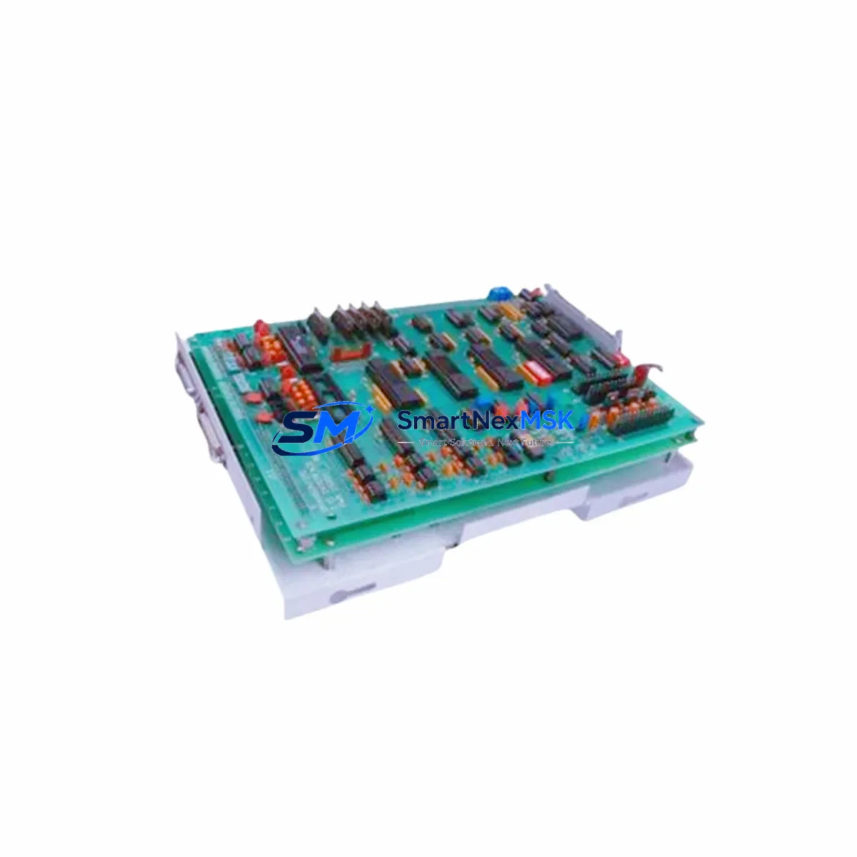
The 804-15005-01 serves as the central control interface within the BRANSON 800 Series ultrasonic welder control cabinet. It governs weld cycle timing, power delivery logic, and process parameter management. Failure of this board typically manifests as erratic weld cycles, loss of amplitude control, fault codes on the HMI panel, or complete system lockout. Identifying and replacing this component promptly is critical to restoring production continuity without requiring full system replacement.
For maintenance engineers managing aging BRANSON 800 Series installations, maintaining a stocked spare of the 804-15005-01 is a standard best practice. Its role in the control architecture means that a single board failure can cascade into broader system faults if not addressed within the maintenance window. Procurement engineers should factor lead time, warranty coverage, and compatibility verification into their spare parts strategy when sourcing this component.
Spare Maintenance Table
| Parameter | Specification / Detail |
|---|---|
| Part Number / SKU | 804-15005-01 |
| Brand | BRANSON |
| Series Compatibility | BRANSON 800 Series Ultrasonic Welding Systems |
| Component Type | PCB Control Board |
| Function | Weld cycle control, power logic, process parameter management |
| Installation Type | Direct board replacement, control cabinet mounted |
| Origin | United States (OEM) |
| Condition | Original spare, functionally tested before shipment |
| Application Environment | Industrial ultrasonic welding, automated assembly lines |
| Maintenance Recommendation | Replace at first sign of weld cycle fault, amplitude loss, or HMI error code |
| Warranty | 12 Months |
| Lead Time | In stock — ready to ship |
Maintenance Planning for Continuous Operation
A disciplined maintenance strategy for BRANSON 800 Series systems extends well beyond the 804-15005-01 control board itself. When performing a board replacement or conducting a scheduled control cabinet inspection, maintenance engineers should simultaneously verify the condition of several interconnected components to prevent secondary failures and reduce the risk of repeat downtime.
The BRANSON power supply module for the 800 Series should be checked for output voltage stability, as an unstable supply is a common root cause of PCB control board degradation. The RF generator assembly and its associated transducer cable should be inspected for insulation integrity and connector condition, since signal anomalies at the transducer interface can stress the control board’s input circuits. The converter/booster stack — including the converter, booster, and horn — should be torque-checked and inspected for wear, as mechanical imbalance can generate electrical feedback that shortens board service life.
Within the control cabinet, the I/O interface board and any installed fieldbus communication module (such as DeviceNet or Profibus adapters used in integrated line configurations) should be seated securely and checked for corrosion on connector pins. The operator panel / HMI assembly should be tested for correct display and input response after the board swap to confirm the control loop is fully restored. Terminal blocks and wiring harnesses connecting the control board to the power section should be inspected for heat damage, loose terminations, or insulation cracking — conditions that are often overlooked during emergency replacements but are a leading cause of premature board failure on reinstallation.
For facilities running multiple 800 Series units, a recommended spare parts inventory includes at minimum: one 804-15005-01 control board, one spare power supply module, one set of replacement fuses for the control circuit, and a spare transducer cable assembly. This inventory posture supports rapid response to both planned and unplanned maintenance events without extended lead time exposure.
Site Replacement Workflow
Replacing the 804-15005-01 in the field is a structured process that, when followed correctly, minimizes total downtime and eliminates the risk of compatibility issues or installation errors.
Step 1 — Fault Isolation: Confirm the 804-15005-01 as the failed component by reviewing the system fault log on the HMI, checking for error codes associated with control board failure, and performing a visual inspection of the board for burn marks, failed capacitors, or damaged traces.
Step 2 — Safe Isolation: De-energize the system following lockout/tagout (LOTO) procedures. Discharge any residual energy in the power section before opening the control cabinet.
Step 3 — Documentation: Photograph the existing wiring and connector layout before disconnecting anything. This is especially important on older 800 Series installations where wiring may have been field-modified over years of service.
Step 4 — Board Removal and Installation: Disconnect all connectors from the 804-15005-01 in sequence, remove the board from its mounting, and install the replacement unit. Reconnect all connectors, verifying each against the documented layout. Confirm that all connector locks are fully engaged.
Step 5 — System Verification: Re-energize the system and perform a controlled test weld cycle at reduced amplitude to verify correct operation before returning the system to full production. Confirm that the HMI displays no fault codes and that weld parameters are within specification.
This workflow is compatible with both direct like-for-like replacement of the 804-15005-01 and scenarios where the board is being installed as part of a broader control system refurbishment or life-extension project on aging 800 Series equipment.
Spare Parts Support FAQ
Q: Is the 804-15005-01 compatible with all variants of the BRANSON 800 Series?
A: The 804-15005-01 is designed for the BRANSON 800 Series ultrasonic welding platform. Compatibility should be verified against your specific machine model and serial number before installation. Our technical team can assist with compatibility confirmation prior to order.
Q: What testing is performed before shipment?
A: Each 804-15005-01 unit is functionally tested prior to dispatch to verify board integrity and operational readiness. A test report is available upon request. All units ship with a 12-month warranty covering manufacturing defects and functional failure under normal operating conditions.
Q: How should the 804-15005-01 be stored as a long-term spare?
A: Store in original anti-static packaging in a dry, temperature-controlled environment away from direct sunlight and electromagnetic interference sources. Inspect the board annually if held in long-term storage and verify connector condition before installation.
Q: What is the recommended spare parts strategy for facilities with multiple 800 Series systems?
A: For facilities operating two or more 800 Series units, maintaining at least one 804-15005-01 on-site as a hot spare is strongly recommended. Pair this with a scheduled inspection cycle — typically aligned with quarterly or semi-annual planned maintenance shutdowns — to proactively identify boards showing early signs of degradation before an unplanned failure occurs.
© 2026 SMARTNEXMSK. All rights reserved.
Original Source: https://smartnexmsk.com
Contact: sales@smartnexmsk.com | +86 18259474341