Bremer Transformatoren UGE100 Retrofit-Ready Voltage Detection for UGE Series Control Systems
The Bremer Transformatoren UGE100 is a retrofit-ready voltage detection module engineered for seamless integration into legacy UGE Series control systems. As industrial facilities face increasing pressure to modernize aging automation infrastructure without full system overhauls, the UGE100 provides a reliable, cost-effective path to upgrade voltage monitoring capabilities while preserving existing control logic, wiring topology, and HMI configurations. Whether you are replacing a discontinued module, recovering from an unplanned failure, or executing a planned control cabinet upgrade, the UGE100 is designed to minimize engineering effort and downtime.
Sourced directly from verified supply channels and subjected to pre-shipment functional testing, each UGE100 unit ships with a 12-month warranty and full traceability documentation. In-stock inventory ensures rapid dispatch to support time-critical maintenance windows and scheduled retrofit projects across Europe, Asia, and global industrial markets.
Upgrade Compatibility Table
| Parameter | Details |
|---|---|
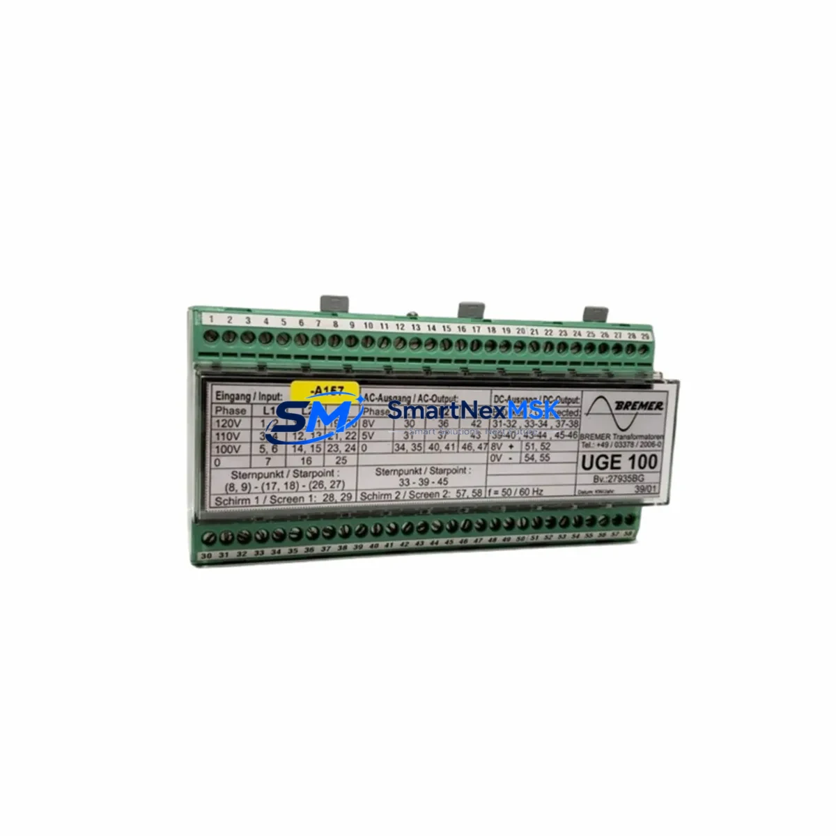
| Compatible Series | Bremer Transformatoren UGE Series |
| Module Function | Voltage Detection / Monitoring |
| Installation Type | DIN Rail / Panel Mount (verify existing mounting footprint) |
| Terminal Wiring | Compatible with standard UGE Series terminal block layout; verify conductor cross-section before installation |
| Communication Interface | Hardwired signal output; confirm signal type (analog/digital) matches existing control loop |
| Backplane / Rack Interface | Standalone module; no backplane bus dependency — verify power supply rail compatibility |
| Replacement Recommendation | Direct drop-in for discontinued UGE Series voltage detection units; confirm firmware/parameter settings if applicable |
| Commissioning Notes | Verify module address assignment, signal scaling, and alarm thresholds in PLC program after installation |
| Warranty | 12 Months from date of shipment |
Retrofit Planning for Existing Automation Systems
Successful integration of the UGE100 into an existing control system requires a structured pre-installation assessment. Begin by auditing the control cabinet layout to confirm available panel space, power supply capacity, and terminal block compatibility. The UGE100 operates within the standard UGE Series power envelope, but engineers should verify that the existing 24 VDC or 230 VAC power supply module — commonly a Bremer Transformatoren or equivalent branded unit — can support the additional load without exceeding rated output current.
Terminal wiring adaptation is a critical step. Review the original wiring diagram and confirm that conductor labeling, cross-section ratings, and terminal positions align with the UGE100 connection scheme. In many retrofit scenarios, the existing terminal block assemblies and cable duct routing can be retained without modification, significantly reducing installation time. Where wiring changes are required, document all modifications in the as-built drawing set before energizing the circuit.
For systems that include a Siemens S7-300 or S7-400 PLC, or equivalent third-party controllers such as an Allen-Bradley ControlLogix or Schneider Electric Modicon M340, the UGE100 signal output must be mapped correctly to the corresponding analog or digital input card. Confirm the I/O module address in the PLC hardware configuration and update the symbol table or tag database accordingly. If the original program references the old module’s I/O address, a program revision will be required — this is typically a minor change but must be validated in a test environment before live deployment.
HMI screens connected to the control system — whether a Siemens SIMATIC HMI TP700, a Weintek cMT series panel, or a SCADA workstation — should be reviewed to confirm that voltage monitoring display tags remain correctly linked after the module swap. In most cases, if the I/O address is preserved, HMI screens require no modification. However, alarm setpoints and engineering unit scaling should be verified against the new module’s output characteristics.
Where the existing system uses a PROFIBUS DP or PROFINET communication backbone, confirm that the UGE100 does not introduce any bus address conflicts. For hardwired signal architectures, this concern does not apply, but the signal cable shielding and grounding scheme should be inspected to prevent noise interference in sensitive measurement circuits. A programming cable and laptop with the appropriate engineering software should be on-site during commissioning to allow real-time monitoring of the input signal and rapid adjustment of scaling parameters.
Downtime Control During System Migration
Minimizing production downtime during a voltage detection module replacement requires careful pre-planning and a disciplined execution sequence. Before scheduling the maintenance window, prepare a complete replacement kit that includes the UGE100 unit, any required terminal adapters, a spare set of fuses, and a copy of the current PLC program backup. Confirm that the backup was taken from the live system — not an outdated archive — to ensure that all recent program modifications are captured.
During the replacement window, follow a structured isolation procedure: de-energize the affected circuit, verify absence of voltage with a calibrated test instrument, remove the failed or obsolete module, and install the UGE100 in its place. Re-energize in stages, monitoring the power supply output and the UGE100 signal output before reconnecting to the PLC input. This staged energization approach allows engineers to detect wiring errors or configuration mismatches before they propagate to the control loop.
Once the module is energized and the signal is confirmed stable, perform a live comparison between the UGE100 output and an independent voltage reference measurement to validate calibration accuracy. Update the PLC program if address or scaling changes were required, download the revised program to the controller, and perform a controlled restart of the affected process section. Document the commissioning results, including measured signal values, alarm test results, and any program changes, in the maintenance record. This documentation supports future audits and simplifies subsequent retrofit cycles.
For facilities operating continuous processes where even brief interruptions are costly, consider pre-staging the UGE100 in a test bench environment to verify its output characteristics before the live installation window. This approach — sometimes called “hot-swap pre-validation” — can reduce the active replacement time to under 30 minutes for experienced technicians.
Retrofit Support FAQ
Q1: Is the UGE100 a direct replacement for all discontinued UGE Series voltage detection modules?
The UGE100 is designed as a retrofit-compatible replacement for the Bremer Transformatoren UGE Series voltage detection range. For specific discontinued model numbers, confirm the terminal pinout, signal output type, and power supply requirements against the UGE100 datasheet before installation. In most cases, the UGE100 is a drop-in replacement with no wiring modifications required.
Q2: What commissioning steps are required after installing the UGE100?
After installation, verify the power supply voltage at the module terminals, confirm the signal output level under known input conditions, check the PLC I/O address mapping, and validate alarm threshold settings. If the system includes an HMI, confirm that voltage display tags are reading correctly. A full functional test under normal operating conditions should be completed before returning the system to production.
Q3: Can the UGE100 be used in systems with mixed communication protocols?
The UGE100 provides a hardwired signal output and does not participate in fieldbus communication protocols such as PROFIBUS, PROFINET, or Modbus. It is compatible with any PLC or controller that accepts the corresponding analog or digital input signal type. Protocol migration activities in the broader control system do not affect UGE100 installation or operation.
Q4: What does the 12-month warranty cover?
Each UGE100 unit is covered by a 12-month warranty from the date of shipment. The warranty covers manufacturing defects and functional failures under normal operating conditions. Pre-shipment testing is performed on every unit to verify electrical performance before dispatch. For warranty claims or technical support, contact our sales team directly.
© 2026 SMARTNEXMSK. All rights reserved.
Original Source: https://smartnexmsk.com
Contact: sales@smartnexmsk.com | +86 18259474341