Brooks 5964CZ67 Retrofit-Ready MFC for 5964 Series Control: Compatible Modernization and Smooth System Upgrade
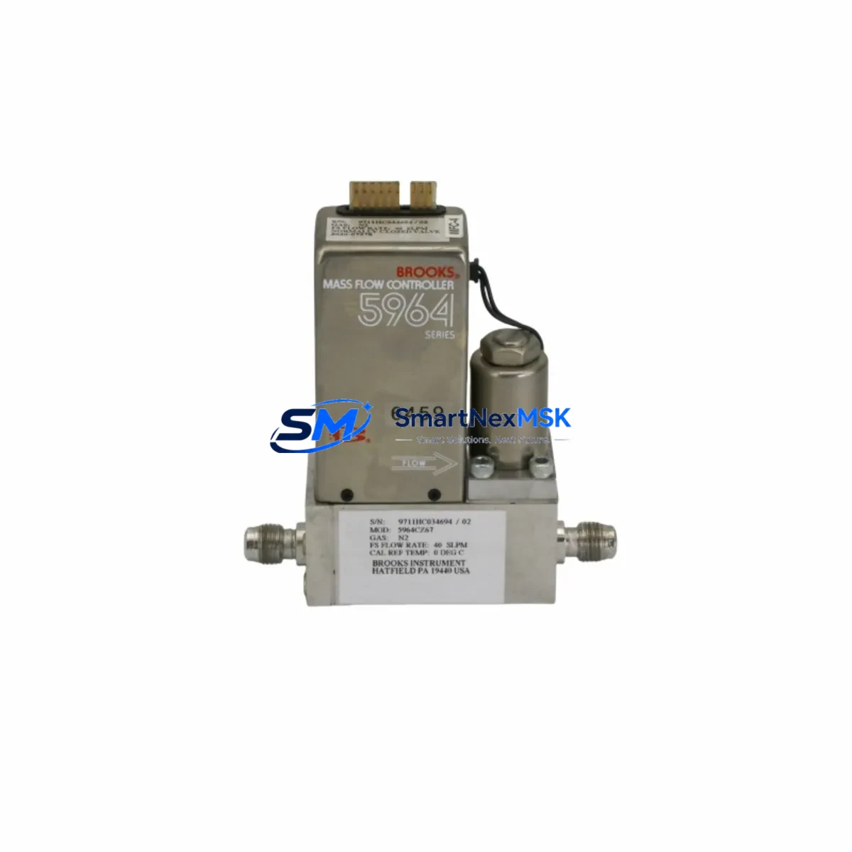
The Brooks Instrument 5964CZ67 is a precision Mass Flow Controller engineered for direct retrofit into existing 5964 Series flow control systems. Whether you are replacing an end-of-life 5964C4KAFR5KA, migrating from an earlier 5964 platform, or upgrading a legacy gas delivery panel in a semiconductor fab, chemical processing line, or analytical instrument enclosure, the 5964CZ67 delivers verified drop-in compatibility with minimal re-engineering. This unit supports N₂ and H₂ gas calibration (reference: GAS N2, 3030-07578) and is stocked for immediate dispatch with a 12-month warranty covering parts and workmanship.
Upgrade Compatibility Table
| Parameter | Legacy Unit (5964C4KAFR5KA) | 5964CZ67 Retrofit Unit | Retrofit Notes |
|---|---|---|---|
| Mounting Interface | D-Net / Surface Mount | D-Net / Surface Mount | Direct mechanical drop-in; no bracket modification required |
| Gas Calibration | N₂ / H₂ (factory) | N₂ / H₂ (GAS N2, 3030-07578) | Confirm gas factor setting in controller software before commissioning |
| Communication Protocol | Analog 0–5 V / RS-485 | Analog 0–5 V / RS-485 | No protocol migration required; verify baud rate and address match |
| Power Supply | ±15 VDC or 24 VDC | ±15 VDC or 24 VDC | Verify rail capacity before installation; check existing PSU headroom |
| Valve Type | Normally Closed | Normally Closed | Fail-safe behavior preserved; no interlock re-programming needed |
| Installation Requirement | Standard panel cutout | Standard panel cutout | Reuse existing gaskets and fittings where condition permits |
| Commissioning Focus | Zero/span calibration | Zero/span calibration | Perform full zero and span verification after installation |
| Warranty | OEM (expired / EOL) | 12-Month Warranty | Covers parts and workmanship from date of shipment |
Retrofit Planning for Existing Automation Systems
Successful integration of the 5964CZ67 into a running production environment requires a structured pre-installation review. Begin by auditing the existing gas panel or flow control manifold to confirm that the upstream pressure regulator, isolation valves, and downstream process connections are compatible with the replacement unit’s inlet/outlet port specifications. In most 5964 Series installations, the manifold block and compression fittings can be reused without modification, significantly reducing retrofit labor time.
Power supply capacity is a critical checkpoint. The 5964CZ67 draws from the same ±15 VDC or 24 VDC rail as its predecessor. Before installation, measure the available headroom on the existing power supply module — particularly in multi-channel racks where several MFCs share a common rail. If the existing PSU is already near capacity, consider replacing it with a higher-rated unit or adding a dedicated secondary supply for the new MFC channel.
Terminal wiring should be mapped against the original wiring diagram. The 5964CZ67 uses the same D-sub or terminal block pinout as the 5964C4KAFR5KA, but always verify signal polarity, setpoint input wiring (0–5 V analog or digital command), and valve override connections before energizing. In systems using a Brooks Smart DDE interface or a third-party flow ratio controller, confirm that the device address and communication parameters (RS-485 baud rate, parity, stop bits) are correctly configured in the host system before the first power-on.
For facilities running a distributed control system (DCS) or PLC-based gas delivery sequence, the replacement MFC must be assigned the correct module address or tag name in the control program. If the original unit was addressed as a specific I/O channel in a Siemens S7 or Allen-Bradley ControlLogix rack, update the hardware configuration in the engineering workstation and perform a forced I/O test before returning the line to automatic mode. HMI faceplate displays tied to the original MFC tag should be verified for correct engineering unit scaling and alarm setpoints after the swap.
In multi-gas systems, the 5964CZ67 may be installed alongside complementary flow components including pressure transducers, manual needle valves, check valves, and secondary MFCs for carrier or purge gas lines. Systems that incorporate a Brooks 0254 or 0152 readout/control unit, or a third-party multi-channel flow controller, should have all channel assignments re-verified after the retrofit. Where the gas panel also includes a mass flow meter (non-controlling) on the same process line, confirm that the meter’s output is not affected by the MFC replacement before resuming flow.
Shipment testing is performed on every 5964CZ67 unit prior to dispatch. Each controller is verified for zero stability, full-scale accuracy, valve response, and leak integrity. Units are shipped with a calibration certificate traceable to NIST standards, and the 12-month warranty begins from the date of shipment.
Downtime Control During System Migration
Minimizing unplanned downtime during an MFC replacement is achievable with disciplined pre-staging. Before the maintenance window opens, confirm that the 5964CZ67 is on-site, the calibration certificate matches the required gas and full-scale range, and all tools, fittings, and wiring documentation are prepared. A pre-staged unit eliminates the most common source of extended downtime: waiting for parts during an active shutdown.
Where process continuity is critical, consider a parallel commissioning approach: install and wire the new 5964CZ67 alongside the existing unit (if panel space permits), configure and verify it in manual mode, then perform a live switchover during a scheduled low-production window. This approach preserves the original control program logic and HMI configuration without requiring a full system restart.
For PLC-controlled sequences, export and archive the current program before any hardware change. If the replacement requires a hardware configuration update in the engineering software (e.g., updating an I/O module address or tag binding), perform this change in a duplicate offline project first and validate it in simulation mode before downloading to the live controller. This protects the original program logic and allows rapid rollback if the commissioning reveals an unexpected compatibility issue.
After installation, perform a controlled ramp-up: start at 10–20% of full-scale setpoint, verify flow response and valve behavior, then step up incrementally to operating setpoint. Log the zero and span readings at each step. This staged approach confirms stable operation before returning the line to full automatic control, and the data serves as a baseline for future preventive maintenance records.
Retrofit Support FAQ
Q1: Is the 5964CZ67 a direct replacement for the 5964C4KAFR5KA without any wiring changes?
In the vast majority of 5964 Series installations, yes. The 5964CZ67 shares the same mechanical footprint, port configuration, and electrical interface as the 5964C4KAFR5KA. However, always cross-reference the original wiring diagram against the replacement unit’s terminal assignment before energizing. Minor label differences between production batches do not affect functional compatibility.
Q2: What commissioning steps are required after installation?
After mechanical installation and wiring verification, perform a zero calibration with the valve closed and no flow, followed by a span check at a known reference flow rate. Confirm the setpoint command signal (analog or digital) is correctly received by the unit and that the output signal matches the expected flow reading in the host system or HMI. Document zero and span values for the maintenance record.
Q3: Can the 5964CZ67 be used with gases other than N₂ and H₂?
The unit is factory-calibrated for N₂ and H₂ (GAS N2, 3030-07578). For other gases, a gas conversion factor (K-factor) can be applied via the controller software or host system, provided the gas is within the compatible viscosity and density range. Contact our technical team to confirm suitability for your specific process gas before ordering.
Q4: What does the 12-month warranty cover, and how is a claim initiated?
The 12-month warranty covers manufacturing defects and workmanship failures from the date of shipment. It does not cover damage resulting from incorrect installation, overpressure, incompatible gases, or unauthorized modification. To initiate a warranty claim, contact sales@smartnexmsk.com with your order reference, unit serial number, and a description of the fault. Replacement or repair will be arranged promptly.
© 2026 SMARTNEXMSK. All rights reserved.
Original Source: https://smartnexmsk.com
Contact: sales@smartnexmsk.com | +86 18259474341