BUSSMANN 170M5715 Retrofit-Ready High-Speed Semiconductor Fuse for 170M Series Control Systems
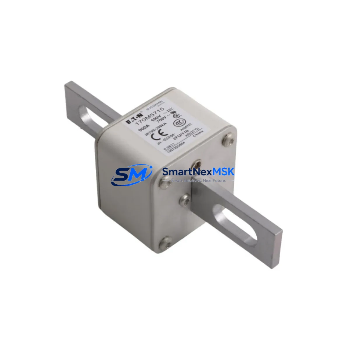
The BUSSMANN 170M5715 is a high-speed semiconductor fuse engineered for direct retrofit and drop-in replacement within 170M Series drive protection circuits. Manufactured by Eaton’s Bussmann division, this fuse is a critical component in modernizing aging power conversion systems, protecting variable frequency drives (VFDs), soft starters, rectifier bridges, and IGBT-based inverter modules from destructive fault currents. Whether you are upgrading a legacy control cabinet, replacing a discontinued spare, or restoring a production line after an unplanned fault event, the 170M5715 delivers verified compatibility and reliable protection without requiring circuit redesign.
Industrial facilities operating older automation platforms — including systems built around Siemens SINAMICS G120, ABB ACS800, Schneider Electric Altivar 71, or Rockwell Allen-Bradley PowerFlex 700 series drives — frequently encounter the challenge of sourcing exact-match semiconductor fuses when original OEM spares are discontinued or on extended lead time. The 170M5715 addresses this directly: its standardized bolt-hole pattern, knife-blade terminal geometry, and current-limiting I²t characteristics align with the protection coordination requirements of these platforms, making it a proven retrofit choice across multiple drive generations.
Upgrade Compatibility Table
| Parameter | Details |
|---|---|
| Part Number | BUSSMANN 170M5715 |
| Series | 170M (Eaton Bussmann High-Speed Semiconductor) |
| Mounting Interface | Knife-blade / bolt-on, standard 170M footprint |
| Terminal Compatibility | Compatible with standard 170M Series fuse holders and DIN-rail fuse bases |
| Communication / Protocol | N/A (passive protection component; no protocol dependency) |
| Replacement Recommendation | Direct drop-in for 170M Series fuses in equivalent current/voltage rating; verify I²t coordination with drive manufacturer specs |
| Installation Requirement | De-energize circuit; verify torque spec on terminal bolts; confirm fuse holder condition before installation |
| Commissioning Note | No firmware or address configuration required; confirm upstream breaker coordination after replacement |
| Warranty | 12-Month Warranty — covers manufacturing defects under normal operating conditions |
Retrofit Planning for Existing Automation Systems
Replacing a blown or end-of-life semiconductor fuse in an active production environment requires more than simply sourcing the correct part number. A structured retrofit plan minimizes risk and ensures the replacement integrates cleanly with the surrounding control architecture.
Before installing the 170M5715, engineers should audit the power supply module feeding the drive cabinet — particularly if the system uses a dedicated 24VDC SITOP PSU or equivalent regulated supply for control logic. Confirm that the supply’s output capacity has not been derated due to age or thermal stress, as an undersized supply can cause nuisance tripping after fuse replacement. Similarly, inspect the input line reactor or EMC filter module upstream of the drive for signs of insulation degradation or loose terminal connections that may have contributed to the original fuse failure.
For systems using PROFIBUS DP or PROFINET IO communication modules integrated into the drive, verify that the communication link remains intact during the replacement window. If the drive is part of a distributed I/O network — for example, using ET 200SP or ET 200M remote I/O stations — coordinate the maintenance window with the PLC program to avoid triggering fault responses in the CPU that could affect other axes or process segments.
In cabinets where the drive shares a common DC bus with regenerative units or braking choppers, the fuse replacement sequence must account for residual DC bus voltage. Use a calibrated multimeter to confirm bus discharge before touching any terminal. If the system includes a brake resistor module or dynamic braking unit, inspect its thermal fuse and connection integrity as part of the same maintenance event — these components are often stressed simultaneously during fault conditions.
For older systems using RS-485 Modbus RTU or DeviceNet communication, document the drive’s node address and baud rate settings before powering down. Some legacy drives lose volatile parameter memory during extended power-off periods, and having a parameter backup — ideally stored on a programming cable or operator panel memory card — prevents extended recommissioning time after the fuse swap.
Finally, if the retrofit involves upgrading from an older fuse generation to the current 170M5715, cross-reference the I²t let-through energy value against the semiconductor device’s withstand rating. This is especially important for IGBT modules in high-power inverters, where marginal I²t coordination can result in repeated fuse failures or, worse, unprotected semiconductor damage.
Downtime Control During System Migration
Unplanned downtime caused by a blown semiconductor fuse is one of the most time-sensitive maintenance scenarios in industrial automation. The 170M5715’s availability from stock — with same-day or next-day dispatch — is a direct response to this operational reality. However, minimizing total downtime requires preparation that begins before the fault occurs.
Facilities that maintain a small buffer stock of critical protection components — including semiconductor fuses, control fuses, and auxiliary contact blocks — consistently achieve faster mean-time-to-repair (MTTR) than those relying solely on on-demand procurement. For high-utilization lines, we recommend holding at least one spare 170M5715 per drive axis as part of a structured critical spares inventory.
During the replacement itself, the most time-consuming steps are typically terminal torque verification, insulation resistance testing, and post-replacement functional validation. Prepare a commissioning checklist in advance: confirm fuse holder condition, check terminal torque to manufacturer specification, perform an insulation resistance test on the motor cable, and execute a no-load test run before returning the drive to production. If the drive’s HMI panel or operator terminal displays a fault history log, clear the fault register and document the event before resuming normal operation.
For systems with redundant drive configurations or bypass contactors, the migration can be executed with zero production impact by switching to the standby path before beginning the fuse replacement. Coordinate with the control room to confirm that the bypass path is fully operational and that the PLC logic governing the switchover is functioning correctly before isolating the faulted drive.
All units supplied by SMARTNEXMSK are subject to pre-shipment functional testing and are covered by a 12-month warranty against manufacturing defects, giving maintenance teams confidence that the replacement component will perform reliably from the first power-on.
Retrofit Support FAQ
Q1: Is the BUSSMANN 170M5715 a direct replacement for my existing 170M Series fuse?
A: In most cases, yes — provided the current rating, voltage rating, and I²t characteristics of the 170M5715 match the original specification. Always cross-reference the drive manufacturer’s recommended fuse table and confirm the fuse holder accepts the 170M knife-blade terminal geometry before installation.
Q2: What wiring or terminal changes are required during installation?
A: The 170M5715 uses the standard 170M Series bolt-on knife-blade interface, so no wiring modifications are required for a like-for-like replacement. Ensure terminal bolts are torqued to the fuse manufacturer’s specification and that the fuse holder contact surfaces are clean and free of oxidation or arc damage.
Q3: How do I verify compatibility with my drive’s protection coordination requirements?
A: Obtain the I²t let-through energy value from the 170M5715 datasheet and compare it against the maximum withstand I²t of the semiconductor device being protected (typically stated in the drive’s technical manual or IGBT module datasheet). If the fuse I²t is lower than the device withstand I²t, the coordination is valid.
Q4: What does the 12-month warranty cover, and how is it claimed?
A: The 12-month warranty covers manufacturing defects under normal operating conditions. It does not cover damage resulting from incorrect installation, overcurrent events beyond the fuse’s rated interrupting capacity, or environmental exposure outside the specified operating range. To initiate a warranty claim, contact our sales team with the order reference, installation date, and a description of the failure mode.
© 2026 SMARTNEXMSK. All rights reserved.
Original Source: https://smartnexmsk.com
Contact: sales@smartnexmsk.com | +86 18259474341