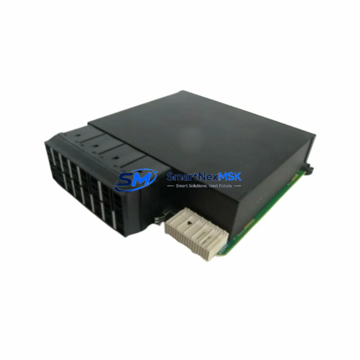
B+W BWU1703 Retrofit-Ready PROFIBUS DP/PA Segment Coupler for BWU Series Control Systems
The B+W BWU1703 is a PROFIBUS DP/PA Segment Coupler engineered for seamless integration into existing process automation architectures. As legacy fieldbus infrastructure ages and OEM support for older BWU-series couplers diminishes, the BWU1703 has become a critical retrofit component for engineers tasked with modernizing distributed control systems without full platform replacement. Whether you are upgrading a DCS backbone, extending a PROFIBUS PA segment in a hazardous area, or replacing a failed coupler in a running production line, the BWU1703 delivers the electrical isolation, signal conversion, and bus management functions required to maintain control continuity.
In retrofit scenarios, the BWU1703 is typically installed to replace earlier-generation DP/PA link modules that no longer meet current EMC standards or that lack the current-sourcing capacity needed for modern PROFIBUS PA field devices. Engineers migrating from older segment couplers must verify the available bus current budget — the BWU1703 supports up to 400 mA on the PA segment, which is sufficient for most standard instrument loops but must be carefully balanced when connecting multiple transmitters, positioners, or flow meters on a single segment. Before installation, confirm that the existing 24 VDC power supply feeding the coupler rail can sustain the combined load of the BWU1703 and all connected PA devices, including devices such as pressure transmitters, temperature heads, and valve positioners that draw continuous bus power.
Terminal wiring compatibility is a key consideration during any coupler swap. The BWU1703 uses standard spring-clamp or screw terminals consistent with the BWU series form factor, but engineers should verify shield grounding topology and cable screen continuity before energizing the PA segment. In older installations, the DP trunk cable may be routed through a PROFIBUS DP repeater or an RS-485 bus terminator — these upstream components remain compatible with the BWU1703 and do not require replacement during a coupler-only retrofit.
Upgrade Compatibility Table
| Parameter | Details |
|---|---|
| SKU / Part Number | BWU1703 |
| Brand / Manufacturer | B+W (Pepperl+Fuchs Group) |
| Product Series | BWU Series PROFIBUS Segment Couplers |
| Interface — DP Side | PROFIBUS DP (RS-485), up to 12 Mbit/s |
| Interface — PA Side | PROFIBUS PA (IEC 61158-2), 31.25 kbit/s |
| PA Segment Bus Current | Up to 400 mA (verify against field device load) |
| Supply Voltage | 24 VDC (nominal); verify existing PSU capacity before swap |
| Installation / Mounting | DIN rail, compatible with standard BWU series backplane |
| Communication Compatibility | PROFIBUS DP V0/V1, PROFIBUS PA profile 3.x |
| Replacement Suitability | Drop-in for BWU series DP/PA couplers; verify GSD file version |
| Commissioning Requirement | GSD file import into engineering tool (e.g., SIMATIC Manager, TIA Portal, PCS 7) |
| Country of Origin | Germany |
| Warranty | 12 Months from date of shipment |
Retrofit Planning for Existing Automation Systems
A successful BWU1703 retrofit begins well before the physical swap. Start by auditing the existing PROFIBUS PA segment topology: document every field device address, confirm that no two devices share the same PA node address, and export the current GSD-based device configuration from your DCS or PLC engineering station. In Siemens-based systems, this typically means exporting the hardware configuration from SIMATIC Manager or TIA Portal before any physical changes are made.
The BWU1703 mounts on a standard DIN rail and connects to the PROFIBUS DP trunk via a standard 9-pin Sub-D connector or terminal block, depending on the existing installation. If the upstream DP master is a Siemens IM 153-2 interface module or a similar remote I/O head station, no DP-side configuration changes are required — the coupler is transparent to the DP master and appears only as a segment boundary. On the PA side, each connected instrument — whether an Endress+Hauser Cerabar pressure transmitter, a Yokogawa EJA differential pressure cell, or an ABB TZIDC valve positioner — retains its existing PA address and GSD profile, provided the BWU1703 firmware is compatible with the PA profile version in use.
For installations that include a PROFIBUS PA junction box or a field barrier assembly, verify that the passive termination resistors at the segment ends are correctly installed and that no active terminators conflict with the BWU1703’s internal termination logic. In multi-drop PA segments, the bus cable impedance and total segment length must remain within IEC 61158-2 limits — typically 1,900 m for standard cable type A. If the existing segment approaches this limit, consider splitting the segment and adding a second BWU1703 coupler rather than extending beyond specification.
When the control system includes a redundant DCS architecture — for example, a Honeywell Experion PKS or an Emerson DeltaV with redundant I/O cards — the BWU1703 retrofit should be coordinated with the redundancy switchover procedure to avoid unplanned failover events during the coupler replacement window. Coordinate with the control room operator to place the affected loop in manual mode before disconnecting the existing coupler.
Downtime Control During System Migration
Minimizing production downtime during a coupler replacement requires a structured hot-swap or planned-outage approach. For non-redundant PA segments, the recommended procedure is to place all PA-connected control loops in manual mode at the DCS or PLC level, document the current process values, and then proceed with the physical coupler swap. The BWU1703 typically initializes within seconds of power-up, and PA device re-enumeration on the segment completes automatically once the DP master resumes cyclic communication.
To protect the original program logic, do not modify the PLC or DCS hardware configuration during the coupler swap — the BWU1703 is designed as a transparent segment coupler and does not require changes to the DP master’s slot/module assignment. If the engineering tool prompts for a hardware reconfiguration after the swap, verify that the GSD file version matches the installed firmware before downloading any changes to the controller. Downloading an incorrect hardware configuration to a running Siemens S7-300 or S7-400 CPU, for example, can cause an unexpected CPU stop and loss of field control.
For sites where continuous operation is mandatory, consider pre-staging the BWU1703 on a test bench with a PROFIBUS PA simulator or a spare field device to verify segment communication before the live installation. This pre-commissioning step, combined with a structured loop check against the existing HMI faceplates, reduces the risk of extended downtime caused by wiring errors or address conflicts discovered only after the coupler is installed in the field.
Retrofit Support FAQ
Q1: Is the BWU1703 a direct drop-in replacement for older BWU series DP/PA couplers?
In most cases, yes. The BWU1703 is mechanically and electrically compatible with the BWU series mounting rail and terminal layout. However, you should verify the GSD file version required by your DCS or PLC engineering tool, as newer firmware versions may require an updated GSD import. No changes to the DP master configuration or PA device addresses are required for a standard coupler swap.
Q2: What wiring checks are required before energizing the BWU1703?
Confirm that the 24 VDC supply voltage is within specification, that the PA segment cable shield is correctly grounded at one end only, that bus terminators are installed at both ends of the PA segment, and that no PA device address conflicts exist. Use a PROFIBUS tester or a laptop with a PROFIBUS diagnostic tool connected via a PC adapter cable to scan the segment before enabling cyclic communication from the DP master.
Q3: How is compatibility with existing HMI screens and DCS faceplates maintained after the retrofit?
Because the BWU1703 is a transparent segment coupler, it does not alter the PA device addresses or GSD-defined process variables visible to the DCS. Existing HMI faceplates, alarm setpoints, and trend historian tags remain valid after the swap. A full loop check — verifying that each PA device’s process value appears correctly on the corresponding HMI faceplate — is recommended as the final commissioning step before returning loops to automatic control.
Q4: What does the 12-month warranty cover, and what pre-shipment testing is performed?
Every BWU1703 unit is function-tested prior to shipment, including power-up verification, DP/PA signal conversion check, and bus current output measurement. The 12-month warranty covers manufacturing defects and component failures under normal operating conditions. Units are shipped with original packaging and, where available, original documentation. For warranty claims, contact our technical support team with the unit serial number and a description of the fault condition.
© 2026 SMARTNEXMSK. All rights reserved.
Original Source: https://smartnexmsk.com
Contact: sales@smartnexmsk.com | +86 18259474341