Carlo Gavazzi SPD2460 SPD24601 Retrofit-Ready DIN Rail Power Supply for SPD Series Control Systems
The Carlo Gavazzi SPD2460 (also catalogued as SPD24601) is a 24 VDC DIN rail-mount power supply engineered for continuous-duty industrial control applications. As legacy SPD Series units reach end-of-service life across manufacturing lines, water treatment facilities, and building automation panels, the SPD2460 / SPD24601 provides a verified drop-in retrofit path that preserves existing wiring layouts, cabinet footprints, and downstream load profiles. SMARTNEXMSK maintains ready stock of this module to support urgent replacement projects with minimal lead time and a 12-month warranty on every unit shipped.
Upgrade Compatibility Table
| Parameter | SPD2460 / SPD24601 | Retrofit Notes |
|---|---|---|
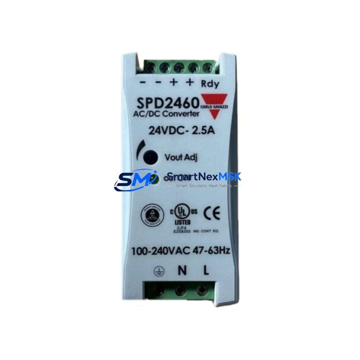
| Output Voltage | 24 VDC regulated | Matches legacy SPD Series output rail; no downstream re-calibration required |
| Output Current | 60 W / 2.5 A continuous | Verify aggregate load of connected I/O modules and relay coils before swap |
| Input Voltage Range | 85–264 VAC / 90–375 VDC wide-range | Compatible with both 110 VAC and 230 VAC panel feeds without jumper change |
| Mounting | 35 mm DIN rail (EN 60715) | Direct replacement on standard TS 35 rail; no bracket adapter needed |
| Terminal Connections | Screw-clamp, 0.2–4 mm² | Existing wire gauges (typically 1.5 mm² or 2.5 mm²) re-terminate without re-crimping |
| Protection Class | IP20 (open-frame DIN) | Suitable for enclosed control cabinets; confirm cabinet IP rating independently |
| Communication / Signal | DC OK relay output (potential-free) | Wire DC OK contact to PLC digital input for power-fault alarming |
| Certifications | CE, UL, cUL | Accepted under existing panel certifications in most jurisdictions |
| Replacement Scope | Direct substitute for SPD2460, SPD24601, and functionally equivalent SPD Series 24 V / 60 W variants | Cross-reference OEM part number before ordering if label is worn |
| Warranty | 12 months from ship date | Covers manufacturing defects; includes pre-shipment load and output-voltage test |
Retrofit Planning for Existing Automation Systems
A successful SPD2460 / SPD24601 retrofit begins well before the maintenance window opens. Start by auditing the existing control cabinet to document every load connected to the 24 VDC bus: digital input cards, analog I/O modules, relay output modules, solenoid valve coils, and any 24 V-powered HMI panels or operator terminals. Sum the steady-state current draw and add a 20 % headroom margin to confirm the 2.5 A output of the SPD2460 is sufficient, or whether a higher-capacity unit from the Carlo Gavazzi SPD Series — such as the SPD24101 (10 A) or SPD24201 (20 A) — is more appropriate for the application.
Inspect the existing DIN rail section. The SPD2460 occupies a standard 35 mm TS 35 rail slot and its width profile is consistent with other Carlo Gavazzi SPD Series modules, so adjacent components such as circuit breakers, terminal blocks, and surge protection devices typically do not need to be relocated. Remove the failed unit, note the L, N, PE, +V, and –V terminal positions, and photograph the wiring before disconnection. The screw-clamp terminals on the SPD24601 accept conductors from 0.2 mm² to 4 mm², covering the 1.5 mm² and 2.5 mm² wire gauges most commonly found in legacy panels.
If the control system includes a Carlo Gavazzi EM Series energy meter, a CP Series controller, or a third-party PLC such as a Siemens S7-300 or Allen-Bradley MicroLogix drawing power from the same 24 V rail, verify that the DC OK relay output of the SPD2460 is wired to a spare digital input on the controller. This allows the PLC program to generate a power-fault alarm rather than experiencing an unexplained I/O dropout. For systems using a Modbus RTU or PROFIBUS DP communication backbone, confirm that the 24 V supply to the communication repeater or gateway module — often a separate DIN rail component — is also within the SPD2460’s load budget.
Panels that include a Carlo Gavazzi RGC Series solid-state relay or a PSR Series soft starter may present inrush current spikes at startup. The SPD2460 incorporates active power factor correction and a hiccup-mode overload response, which handles brief inrush events without nuisance tripping. However, if the panel also powers a frequency inverter’s 24 V control circuit, confirm the inverter manufacturer’s isolation requirements before sharing the supply rail.
For retrofit projects involving older Carlo Gavazzi CPCE or CPCF Series programmable controllers, the SPD2460 is a recognized compatible power source. Ensure the programming cable — typically a USB-to-RS232 adapter for legacy CPCE units — is available on-site before the maintenance window, as re-downloading the application program may be required if the controller loses its RAM backup during the power interruption. Back up the PLC program, HMI screen project, and any recipe data to a laptop or USB drive before beginning the physical swap.
Downtime Control During System Migration
Minimizing unplanned downtime during a power supply replacement requires a structured sequence. Schedule the swap during a planned maintenance window and notify all stakeholders of the expected outage duration — typically 30 to 90 minutes for a straightforward SPD2460 replacement in an accessible cabinet. Before de-energizing the panel, place the process in a safe hold state: close control valves, park moving axes at home positions, and confirm that any safety relay or emergency-stop circuit will not interpret the power interruption as a fault requiring manual reset.
Use a portable 24 VDC bench supply connected in parallel to the output bus to maintain power to the PLC CPU and communication modules while the failed supply is removed. This technique — sometimes called a hot-swap bridge — keeps the controller in RUN mode, preserves the program execution state, and prevents the HMI from losing its communication link to the controller. It is particularly valuable in systems where a cold restart triggers a lengthy homing sequence or a batch process initialization routine.
Once the SPD2460 / SPD24601 is installed and terminals are torqued to specification, remove the bridge supply, restore mains power, and verify the DC OK contact closes within the expected time (typically under 2 seconds). Check output voltage at the terminal block with a calibrated multimeter — the SPD2460 output is factory-set to 24.0 V ± 1 % and is adjustable via the front-panel trimmer if the downstream load requires a slightly elevated rail. Confirm all I/O modules, communication gateways, and HMI panels resume normal operation before returning the process to automatic mode. Document the replacement in the panel’s maintenance log, including the new unit’s serial number and the 12-month warranty expiry date.
Retrofit Support FAQ
Q1: Is the SPD2460 a direct drop-in replacement for the SPD24601, and are there any wiring differences?
The SPD2460 and SPD24601 are the same product — SPD24601 is the full catalogue reference (SPD + 24 V + 60 W + 1 output) while SPD2460 is the abbreviated commercial designation. Terminal layout, DIN rail footprint, and electrical ratings are identical. No wiring changes are required when substituting one designation for the other.
Q2: What pre-shipment testing does SMARTNEXMSK perform on the SPD2460 / SPD24601?
Every unit undergoes a full-load output voltage test, DC OK relay function verification, and input wide-range acceptance test (85 VAC and 264 VAC) before dispatch. A test report is available on request. The 12-month warranty covers manufacturing defects and any failure attributable to the unit itself under normal operating conditions.
Q3: Can the SPD2460 power a mixed load of Carlo Gavazzi I/O modules and a third-party PLC simultaneously?
Yes, provided the total steady-state current draw remains below 2.5 A (60 W at 24 VDC). The SPD2460’s wide-range input and regulated output are compatible with any 24 VDC load regardless of manufacturer. For mixed-brand panels, verify that the PLC’s 24 V input is not internally connected to its logic ground in a way that conflicts with the SPD2460’s negative output terminal grounding scheme.
Q4: How do I confirm compatibility if the original unit’s label is unreadable?
Measure the output voltage (24 VDC), check the DIN rail width (35 mm), and note the terminal count and positions. Cross-reference the cabinet wiring diagram or the original panel builder’s BOM. If the original unit was any Carlo Gavazzi SPD Series 24 V / 60 W single-output module, the SPD2460 / SPD24601 is the correct replacement. Contact sales@smartnexmsk.com with photos of the unit and cabinet label for a free compatibility confirmation before ordering.
© 2026 SMARTNEXMSK. All rights reserved.
Original Source: https://smartnexmsk.com
Contact: sales@smartnexmsk.com | +86 18259474341