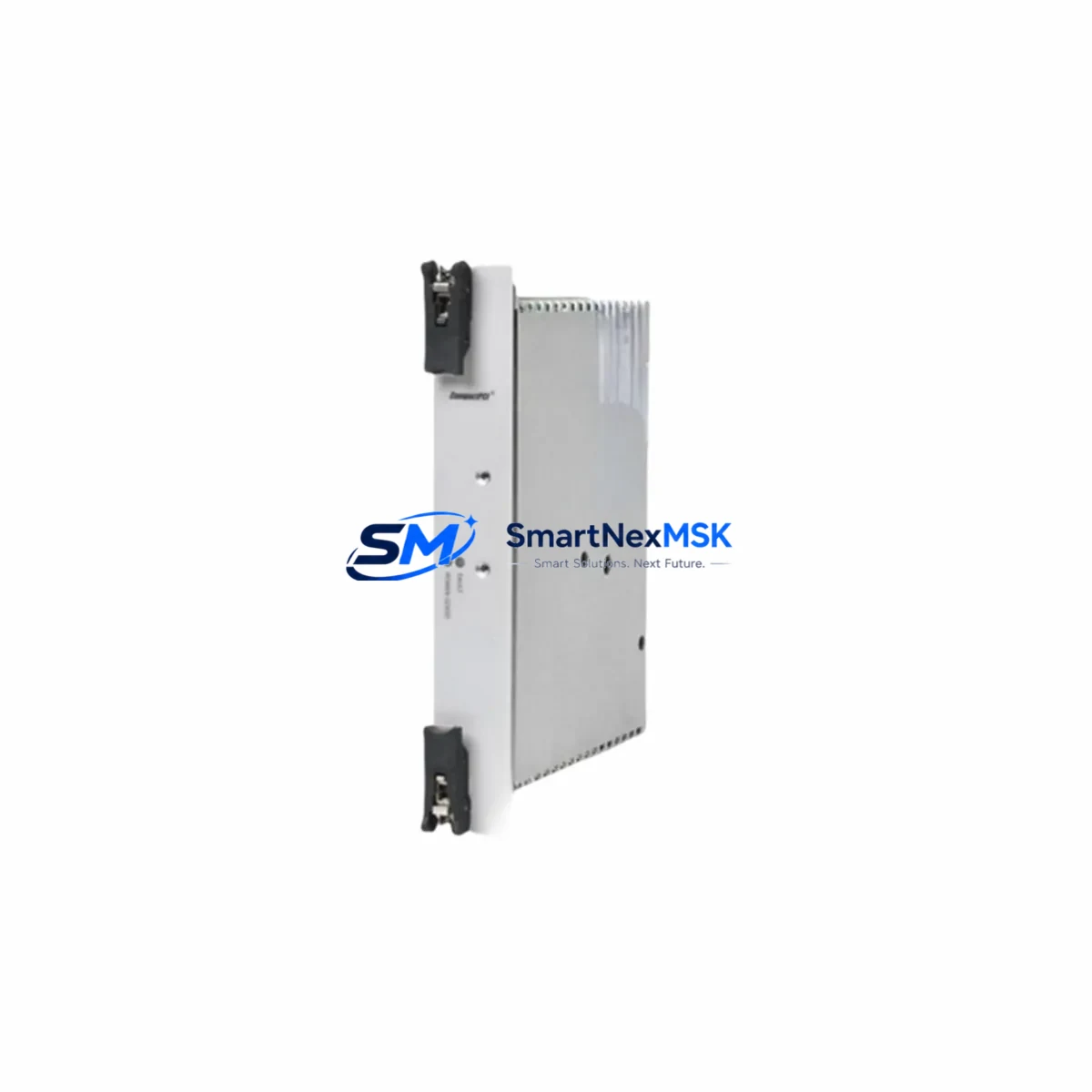
CompactPCI SC2435-1-S Retrofit-Ready Embedded Controller for SC2435 Control Systems
The CompactPCI SC2435-1-S is a retrofit-ready embedded controller engineered for seamless integration into existing SC2435-series control architectures. Designed to address the growing demand for legacy system modernization, this module delivers a direct, wiring-compatible upgrade path for facilities operating aging CompactPCI backplane infrastructures. Whether you are replacing a discontinued SC2435 controller, expanding I/O capacity in a legacy control cabinet, or migrating communication protocols to meet current plant standards, the SC2435-1-S provides the compatibility, reliability, and supply assurance that industrial engineers require.
Sourced directly from verified supply channels and subject to full functional testing prior to dispatch, each SC2435-1-S unit ships with a 12-month warranty covering hardware defects and operational failures under normal industrial conditions. Inventory is maintained in stock to support urgent retrofit schedules, minimizing procurement lead times for time-sensitive plant shutdowns or emergency replacements.
Upgrade Compatibility Table
| Parameter | Details |
|---|---|
| SKU / Part Number | SC2435-1-S |
| Series Compatibility | CompactPCI SC2435 Series |
| Form Factor | CompactPCI (cPCI) 3U / 6U — confirm slot pitch with existing chassis |
| Backplane Interface | CompactPCI J1/J2 connector; verify rear I/O transition module alignment |
| Power Requirements | +5 VDC / +3.3 VDC via backplane; confirm PSU capacity before installation |
| Communication Compatibility | Supports legacy serial (RS-232/RS-485) and Ethernet-based protocols; verify fieldbus mapping if migrating from PROFIBUS or CANopen |
| I/O Expansion | Compatible with standard cPCI I/O expansion modules in the same chassis |
| Installation Requirement | Hot-swap capability subject to chassis support; cold-swap recommended for first-time retrofit |
| Replacement Recommendation | Direct replacement for SC2435 series; re-address module slot if chassis mapping has changed |
| Commissioning Notes | Reload original PLC program; verify HMI tag bindings and communication node addresses post-swap |
| Warranty | 12 months from date of shipment — hardware defects and operational failures covered |
Retrofit Planning for Existing Automation Systems
Successful retrofit of the SC2435-1-S into an operational control system requires systematic pre-installation planning. Before removing the legacy SC2435 controller, engineers should document the existing backplane slot assignments, terminal wiring labels, and module address configuration stored in the PLC program. In many legacy installations, the SC2435 controller shares a chassis with companion modules such as analog input/output cards, digital I/O expansion boards, and dedicated communication interface modules — all of which must remain undisturbed during the controller swap.
Power supply capacity is a critical verification step. The existing CompactPCI power supply module must be confirmed to deliver sufficient current on the +5 VDC and +3.3 VDC rails to support the SC2435-1-S alongside all co-installed modules. In aging control cabinets, power supply derating over time can result in marginal headroom that causes instability after a new module is introduced. If the existing PSU is near its rated capacity, replacement with a higher-rated cPCI power supply should be planned concurrently.
For systems using a CompactPCI backplane with rear transition modules, the physical alignment of the J2 connector and any rear I/O breakout boards must be verified against the SC2435-1-S pinout. Mismatched rear I/O transition cards are a common source of commissioning delays in legacy retrofits. Where the original rear I/O board is no longer available, a compatible cPCI rear transition module may need to be sourced as part of the upgrade bill of materials.
Communication protocol continuity is equally important. If the existing system relies on a PROFIBUS DP communication module or a CANopen network interface card installed in an adjacent chassis slot, the SC2435-1-S must be confirmed compatible with the master/slave addressing scheme in use. In cases where the legacy controller managed the communication master role, the replacement unit must be configured to assume the same node address and baud rate settings before the system is brought back online.
HMI integration is another area requiring pre-retrofit attention. Facilities running SIMATIC WinCC, iFIX, or other SCADA platforms connected to the SC2435 via OPC or direct serial links must verify that the HMI tag database references the correct communication driver and device address after the controller swap. In some installations, the HMI project file must be updated to reflect the new controller’s network identity before operator screens will display live data correctly.
For I/O-intensive applications, the SC2435-1-S can be paired with cPCI digital input modules and cPCI analog output modules to restore or expand the original I/O count. Where the legacy system used a CompactPCI serial communication module for RS-485 Modbus RTU links to field instruments, this module should be retained in its original slot to preserve the existing wiring and instrument addressing without modification.
Finally, a programming cable compatible with the SC2435-1-S is required for initial configuration and program upload. Confirm the programming interface — USB, Ethernet, or legacy RS-232 — and ensure the engineering workstation has the appropriate software version installed before the maintenance window begins.
Downtime Control During System Migration
Minimizing unplanned downtime is the primary operational concern in any legacy controller replacement. A structured migration approach for the SC2435-1-S begins with a full backup of the existing PLC program, including all data blocks, function blocks, hardware configuration files, and symbol tables. This backup should be stored on at least two independent media before any physical work begins.
Where the production schedule permits, a bench test of the SC2435-1-S using a spare chassis or test rack — populated with representative I/O modules and a test power supply — allows engineers to validate the program upload, communication configuration, and I/O response before the unit enters the live control cabinet. This pre-commissioning step is the single most effective method for compressing on-site installation time and reducing the risk of extended downtime caused by configuration errors discovered during live commissioning.
During the physical swap, the sequence of operations should follow a defined lockout/tagout procedure. After de-energizing the chassis, the legacy SC2435 is removed, the SC2435-1-S is seated and secured, and power is restored in a controlled sequence. The PLC program is then uploaded from the backup, communication parameters are verified against the documented node address table, and each I/O channel is tested against the field wiring before the system is returned to automatic control.
For systems where continuous process control is required, a parallel operation strategy — running the SC2435-1-S in a shadow configuration alongside the legacy controller before cutover — can further reduce transition risk. This approach requires careful management of I/O write conflicts but provides the highest level of continuity assurance for critical production lines.
All SC2435-1-S units supplied by SMARTNEXMSK undergo functional testing prior to shipment, including power-on verification and communication interface checks, to ensure the unit arrives ready for installation without additional incoming inspection delays.
Retrofit Support FAQ
Q1: Is the SC2435-1-S a direct drop-in replacement for the original SC2435 controller?
The SC2435-1-S is designed as a compatible replacement for the SC2435 series. Physical form factor, backplane connector, and power rail requirements are consistent with the original specification. However, engineers should verify the module slot address assignment and rear I/O transition module compatibility before installation, as chassis configurations may vary between installations.
Q2: What commissioning steps are required after installing the SC2435-1-S?
After physical installation, the original PLC program must be uploaded to the SC2435-1-S. Communication node addresses, baud rates, and protocol settings must be verified and matched to the existing network configuration. HMI tag bindings and SCADA communication drivers should be tested against live I/O before returning the system to automatic operation. A full I/O channel verification against field wiring is recommended as the final commissioning step.
Q3: Does the SC2435-1-S support the same wiring terminations as the legacy SC2435?
The SC2435-1-S uses the standard CompactPCI backplane interface, and field wiring connects via the existing terminal blocks or rear transition modules in the control cabinet. In most installations, no rewiring is required. Where rear I/O transition modules are in use, the pinout compatibility of the transition card with the SC2435-1-S should be confirmed against the module’s technical datasheet before installation.
Q4: What does the 12-month warranty cover, and what is the process for warranty claims?
The 12-month warranty covers hardware defects and operational failures under normal industrial operating conditions from the date of shipment. Units that fail during the warranty period are eligible for replacement or repair. To initiate a warranty claim, contact SMARTNEXMSK at sales@smartnexmsk.com with the order reference, unit serial number, and a description of the fault. Replacement units are dispatched subject to stock availability and fault verification.
© 2026 SMARTNEXMSK. All rights reserved.
Original Source: https://smartnexmsk.com
Contact: sales@smartnexmsk.com | +86 18259474341