Delem DA-51 8051-006 Retrofit-Ready HMI for DA-51 Control Systems: Compatible Modernization & Smooth Legacy Upgrade
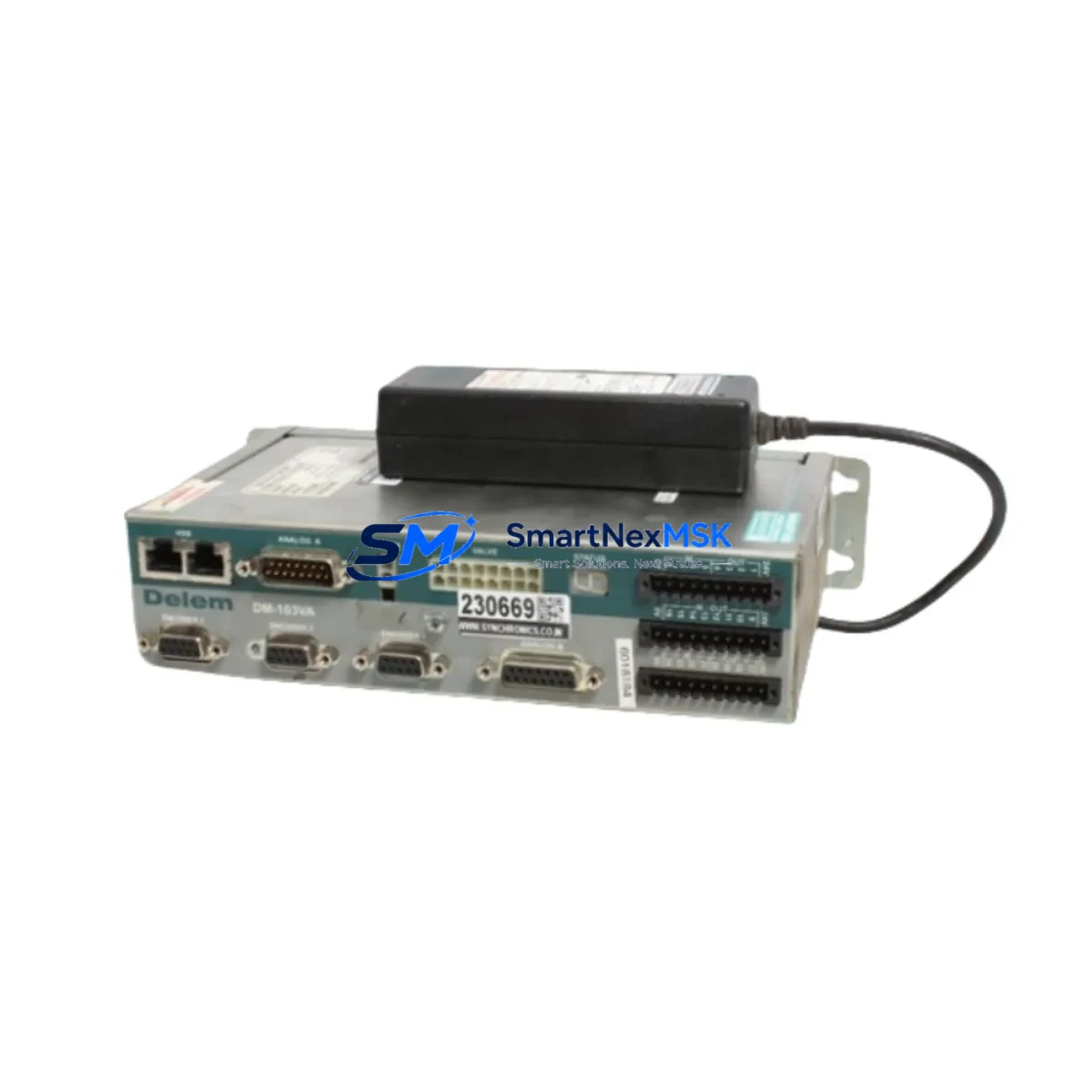
The Delem DA-51 8051-006 is a retrofit-ready HMI display module engineered for seamless integration into DA-51 series CNC press brake control systems. As original DA-51 units age out of manufacturer support and spare parts become increasingly scarce, the 8051-006 display assembly provides a verified drop-in replacement path that preserves existing machine logic, operator interface layouts, and bending programs without requiring a full controller overhaul. Whether you are recovering a production line from an unexpected display failure, executing a planned control cabinet upgrade, or migrating a legacy press brake fleet to a maintainable spare-parts ecosystem, the DA-51 8051-006 delivers the compatibility, reliability, and supply continuity that industrial maintenance teams demand.
Delem’s DA-51 platform has been widely deployed across sheet metal fabrication facilities worldwide, and the 8051-006 display board is a critical serviceable component within that ecosystem. Our stock is sourced, inspected, and dispatch-tested before shipment, backed by a 12-month warranty covering manufacturing defects and functional failures under normal operating conditions.
Upgrade Compatibility Table
| Parameter | Details |
|---|---|
| SKU / Part Number | DA-51 8051-006 |
| Compatible Controller Series | Delem DA-51 (all sub-variants) |
| Module Function | HMI Display Assembly — operator interface panel |
| Interface / Connector | OEM-matched ribbon and board connectors; no adapter required for standard DA-51 backplane |
| Installation Requirement | Direct panel swap; retain original mounting hardware and cable harness |
| Communication Compatibility | Compatible with DA-51 internal bus; no protocol reconfiguration required |
| Replacement Recommendation | Suitable for failed, cracked, or unresponsive original 8051-006 display units |
| Commissioning Notes | Verify display address settings match original unit; restore bending program backup before power-on |
| Warranty | 12 months from date of dispatch — covers manufacturing defects and functional failure |
| Pre-Shipment Test | Power-on functional verification performed on every unit before dispatch |
| Origin | Netherlands (Delem BV) |
Retrofit Planning for Existing Automation Systems
A successful DA-51 8051-006 display retrofit begins well before the replacement unit arrives on site. Maintenance engineers should start by documenting the current DA-51 controller configuration: capture all bending programs stored in the controller memory, photograph the existing wiring harness routing inside the control cabinet, and record any custom axis parameters or machine-specific calibration values saved in the DA-51 system memory. This preparation eliminates the most common source of extended downtime — the loss of production programs during a hardware swap.
Inside a typical DA-51 press brake control cabinet, the display module interfaces with the main DA-51 CPU board via a dedicated ribbon cable assembly. Before disconnecting the original 8051-006 unit, confirm that the DA-51 power supply module is de-energized and that the 24 VDC auxiliary rail serving the HMI panel has been isolated. Many DA-51 installations also include a DA-51 I/O expansion module that handles footswitch inputs, safety relay feedback, and stroke-limit signals — these I/O connections are independent of the display swap and should remain undisturbed throughout the procedure.
For press brakes that use a Delem DA-56 or DA-58 as the primary bending controller alongside a DA-51 display sub-system, technicians should verify that the inter-controller communication link — typically an RS-232 or RS-422 serial connection — is re-established and tested after the display replacement. Similarly, installations that have integrated a Delem DA-65W or DA-66T touch-screen controller as a supervisory HMI should confirm that the DA-51 axis data is still correctly mirrored to the supervisory display after the 8051-006 swap.
Control cabinets housing DA-51 systems often also contain a Delem DA-2S or DA-2x back-gauge controller for X-axis and R-axis positioning. These back-gauge controllers communicate with the DA-51 via a dedicated serial link, and their address configuration must be verified against the replacement display’s internal DIP switch or jumper settings to prevent address conflicts on the control bus. Additionally, if the press brake uses a Delem programming cable (USB-to-DA or RS-232-to-DA adapter) for offline program transfer, confirm that the cable driver and transfer software version are compatible with the restored DA-51 firmware before attempting a program upload.
Facilities that operate multiple press brakes on a shared DNC (Distributed Numerical Control) network should also verify that the machine’s network node address and baud rate settings are correctly restored after the display replacement, particularly if the DA-51 unit stores these parameters in display-side non-volatile memory rather than on the CPU board. Where a Delem DA-51 front panel keypad membrane shows wear alongside the display failure, it is advisable to replace both components simultaneously to avoid a second unplanned shutdown within a short interval.
Downtime Control During System Migration
Minimizing press brake downtime during a DA-51 8051-006 display replacement requires a structured pre-swap checklist and a clear rollback plan. The following approach has been validated across multiple DA-51 retrofit projects in sheet metal fabrication environments:
Step 1 — Program Backup: Use the DA-51’s built-in program export function or a compatible Delem programming cable to transfer all bending programs to an external storage medium before powering down the machine. Confirm that the backup file is readable and complete before proceeding.
Step 2 — Parameter Documentation: Record all machine parameters visible in the DA-51 service menu, including axis gain settings, crowning compensation values, and safety relay timing parameters. These values are machine-specific and cannot be recovered from a replacement display unit.
Step 3 — Controlled Shutdown: Follow the DA-51 shutdown sequence to ensure that the controller completes any pending write operations to non-volatile memory before power is removed. Abrupt power loss during a write cycle can corrupt the parameter store on the CPU board, compounding the repair scope.
Step 4 — Display Swap: Disconnect the ribbon cable and power connector from the original 8051-006 unit, install the replacement module, and secure all connectors before applying power. Do not force connectors — the DA-51 display interface is keyed, and misalignment will damage the connector pins.
Step 5 — Commissioning and Verification: Power on the DA-51 system and confirm that the display initializes correctly, all axis positions are read accurately, and the operator interface responds to keypad inputs. Restore the bending program backup and run a dry-cycle (no material, no clamping force) to verify that the machine executes the program sequence correctly before returning the press brake to production.
By following this sequence, most DA-51 8051-006 display replacements can be completed within a single shift, keeping unplanned downtime to a minimum and protecting the continuity of production schedules.
Retrofit Support FAQ
Q1: Is the DA-51 8051-006 a direct drop-in replacement for the original Delem display, or does it require firmware updates?
The 8051-006 is designed as a direct replacement for the original DA-51 display assembly. In most standard DA-51 installations, no firmware update is required. However, if the existing DA-51 CPU board is running a firmware version that is significantly older than the display module’s embedded firmware, Delem’s field service documentation recommends verifying firmware compatibility before commissioning. Contact our technical team with your DA-51 CPU board serial number and we will confirm compatibility before dispatch.
Q2: What wiring checks should be performed before installing the replacement display?
Before installing the DA-51 8051-006 replacement, inspect the ribbon cable connecting the display to the CPU board for signs of wear, cracking, or pin damage. A damaged ribbon cable is a common secondary cause of display failure and should be replaced simultaneously if any damage is found. Also verify that the 5 VDC and 12 VDC supply rails on the DA-51 power supply module are within specification — an out-of-tolerance power supply can damage a new display module within hours of installation.
Q3: Can the DA-51 8051-006 be used as a replacement in DA-51 controllers that have been integrated with third-party safety systems or servo drives?
Yes. The DA-51 8051-006 display module interfaces exclusively with the DA-51 CPU board and does not directly communicate with third-party safety PLCs, servo amplifiers, or hydraulic valve controllers. Replacing the display module does not alter the signal paths between the DA-51 CPU and any external safety or motion control hardware. However, after the display swap, always perform a full safety function test — including emergency stop, two-hand control, and light curtain response — before returning the machine to operator use.
Q4: What does the 12-month warranty cover, and what is the process for a warranty claim?
The 12-month warranty covers manufacturing defects and functional failures under normal operating conditions from the date of dispatch. It does not cover damage caused by incorrect installation, out-of-specification supply voltages, physical impact, or unauthorized modification. To initiate a warranty claim, contact sales@smartnexmsk.com with your order number, a description of the failure symptom, and photographs of the installed unit. Our team will assess the claim and arrange a replacement or repair within the warranty terms.
© 2026 SMARTNEXMSK. All rights reserved.
Original Source: https://smartnexmsk.com
Contact: sales@smartnexmsk.com | +86 18259474341