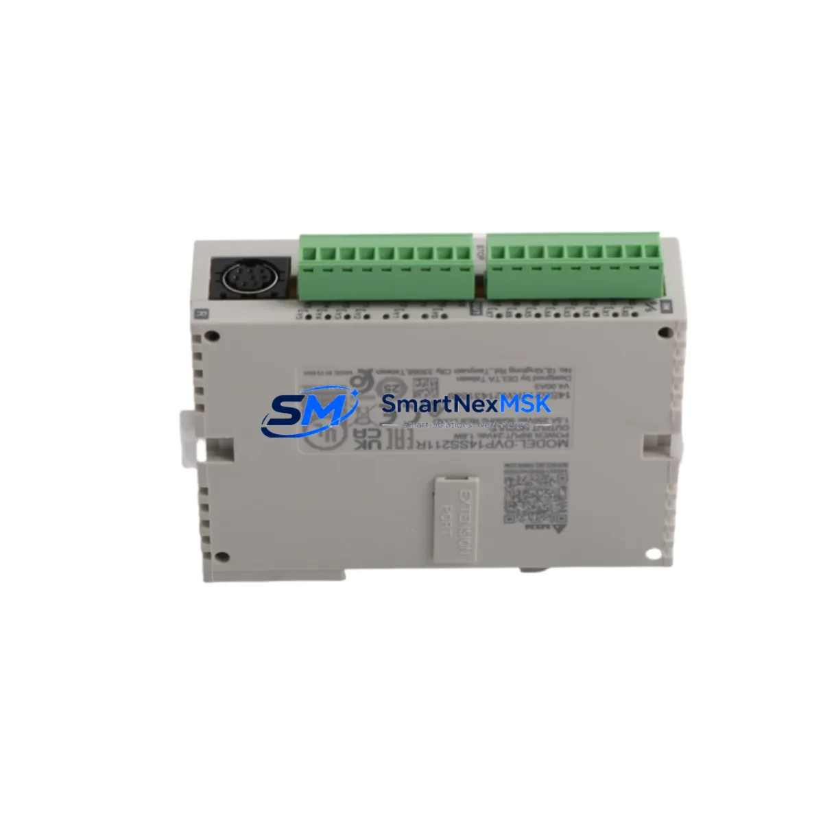
DELTA DVP14SS211R Retrofit-Ready Relay PLC for DVP-SS2 Control Systems
The DELTA DVP14SS211R is a compact, high-reliability 14-point I/O slim PLC module engineered for seamless integration into existing DVP-SS2 series control architectures. Designed with industrial retrofit engineers in mind, this unit delivers a direct compatibility path for aging DVP-SS2 installations, discontinued relay output controllers, and legacy control cabinets that require a verified drop-in upgrade without full system redesign. Whether you are managing a production line modernization, replacing an end-of-life controller, or expanding I/O capacity in a constrained panel space, the DVP14SS211R provides the electrical, mechanical, and software compatibility required to minimize engineering risk and reduce commissioning time.
With 8 digital inputs and 6 relay outputs in a slim DIN-rail form factor, the DVP14SS211R supports RS-485 communication via the MODBUS RTU protocol, making it fully interoperable with existing HMI panels, SCADA systems, and upstream controllers already deployed in your facility. Its onboard programming port accepts the standard DVP programming cable, ensuring that existing WPLSoft or ISPSoft ladder logic programs can be transferred, verified, and re-deployed without rewriting control logic from scratch.
Upgrade Compatibility Table
| Parameter | DVP14SS211R (This Unit) | Retrofit Notes |
|---|---|---|
| I/O Configuration | 8 DI / 6 Relay DO | Matches DVP-SS2 standard 14-pt relay layout |
| Power Supply | 24V DC | Verify existing PSU capacity ≥ 500mA for this module |
| Communication | RS-485 MODBUS RTU | Compatible with existing HMI and SCADA links |
| Programming Interface | RS-232 / USB via adapter | Use standard DVP programming cable; WPLSoft/ISPSoft supported |
| DIN Rail Mounting | Standard 35mm DIN | Direct fit; no bracket modification required |
| Backplane / Rack | Standalone (no backplane) | Confirm terminal block pitch matches existing wiring harness |
| Module Address | Configurable via rotary switch | Set to match original node address before power-on |
| Replacement Compatibility | DVP14SS211R / DVP-SS2 series | Verified drop-in for DVP14SS211T (transistor) with wiring review |
| Commissioning Focus | Program upload, I/O force test, comms check | Validate all field devices before returning to AUTO mode |
| Warranty | 12 Months | Covers manufacturing defects; DOA replacement within 7 days |
Retrofit Planning for Existing Automation Systems
Successful retrofit of the DVP14SS211R into an operational control system begins with a thorough pre-replacement audit. Before removing the original controller, engineers should document the existing terminal wiring layout, confirm the 24V DC power supply rail can sustain the module’s current draw alongside co-installed devices such as the DVP-PS02 power supply module or equivalent slim-series PSU. In multi-drop RS-485 networks, the node address of the original unit must be recorded and replicated on the replacement module’s rotary address switch prior to installation.
For systems using expansion I/O, verify that any attached DVP08SM11N digital input expansion or DVP08SP11R relay output expansion modules remain electrically and logically compatible with the DVP14SS211R’s left-side expansion bus. The expansion connector pinout and communication handshake protocol are consistent across the DVP-SS2 family, but physical seating and locking tab condition should be inspected before power-up.
In control cabinets where the DVP14SS211R shares panel space with a DELTA DOP-B series HMI or a DVP-SV2 series motion controller, confirm that the RS-485 network topology remains within the 32-node limit and that termination resistors are correctly placed at both ends of the communication bus. If the original system used a DVP-F232 RS-232 to RS-485 converter for upstream SCADA connectivity, this converter remains fully compatible and does not require replacement.
Terminal block wiring should be re-terminated using the original wire gauge and ferrule specifications. The DVP14SS211R’s screw terminal pitch is consistent with the DVP-SS2 series, allowing the existing wiring harness to be reconnected without re-crimping in most installations. For systems where the original controller was paired with a DVP-DNET01 DeviceNet communication module or a DVP-PROFIBUS-SL communication card, protocol migration planning is required, as the DVP14SS211R’s native communication is RS-485 MODBUS RTU only. In these cases, a protocol gateway or communication bridge module should be specified as part of the upgrade bill of materials.
Before final commissioning, upload the backed-up ladder logic program via WPLSoft or ISPSoft, perform a full I/O force test to verify all field devices respond correctly, and confirm that HMI screen tag addresses map correctly to the new controller’s memory registers. Pay particular attention to any special function registers (D registers, M relays) that may have been used for communication status flags or timer presets in the original program.
Downtime Control During System Migration
Minimizing production downtime during a DVP14SS211R retrofit requires a structured hot-swap preparation protocol. Prior to the scheduled maintenance window, back up the complete PLC program from the original controller using WPLSoft’s upload function and store a verified copy on both a local engineering laptop and a secure network location. Document all current I/O force values, timer presets, and counter accumulator values that may be active during normal operation, as these will need to be restored or re-initialized after the replacement unit is powered on.
During the physical swap, label all terminal wires before disconnection to eliminate re-wiring errors under time pressure. The DVP14SS211R’s terminal layout mirrors the original DVP-SS2 relay output module, so a pre-printed terminal map significantly reduces reconnection time. After mechanical installation and wiring reconnection, set the module address rotary switch, apply 24V DC power, and confirm the RUN/STOP LED status before downloading the program. Perform a controlled I/O test in STOP mode using forced outputs to verify all actuators and field devices respond correctly before switching to RUN mode.
For critical production lines where even a brief interruption is unacceptable, consider pre-staging a fully programmed and tested DVP14SS211R on a bench test rig using a DVP-SS2 series simulator or a spare I/O wiring harness. This approach allows the replacement unit to be validated against the actual control program before the maintenance window begins, reducing in-field commissioning time to under 30 minutes in most installations. Maintaining a spare DVP14SS211R in local inventory — alongside commonly paired components such as the DVP-PS02 power supply and DVP08SM11N expansion module — further reduces mean time to repair (MTTR) for unplanned failures.
Retrofit Support FAQ
Q1: Is the DVP14SS211R a direct drop-in replacement for the DVP14SS211T?
The DVP14SS211R (relay output) and DVP14SS211T (transistor output) share the same housing, power supply requirements, and communication interface, but differ in output type. Relay outputs are suitable for AC/DC load switching up to 2A per point, while transistor outputs are optimized for high-speed DC switching. If your original installation used transistor outputs for pulse train or high-frequency switching applications, the relay output variant may not be a functional substitute. For standard on/off control of motors, solenoids, and contactors, the DVP14SS211R is a verified replacement.
Q2: Can I reuse my existing WPLSoft program without modification?
In most cases, yes. Programs developed for DVP-SS2 series controllers are fully compatible with the DVP14SS211R without instruction set changes. However, if the original program used firmware-specific special function blocks or communication function codes tied to a specific firmware version, verify the firmware revision of the replacement unit matches or exceeds the original. Firmware updates can be applied via the programming port using DELTA’s firmware update utility.
Q3: What wiring checks are required before powering on the replacement unit?
Before applying power, verify: (1) 24V DC supply polarity on the power terminals, (2) all relay output common terminals are correctly connected to the load power supply, (3) input commons are tied to the correct reference voltage, (4) RS-485 A/B polarity is consistent with the existing network wiring, and (5) the module address rotary switch matches the original node address. A continuity check on all terminal connections before power-up is strongly recommended.
Q4: What does the 12-month warranty cover, and what is the DOA process?
The 12-month warranty covers manufacturing defects, component failures under normal operating conditions, and firmware integrity. It does not cover damage caused by incorrect wiring, overvoltage, physical impact, or unauthorized modification. Units that arrive dead-on-arrival (DOA) are eligible for express replacement within 7 business days upon confirmation of the fault condition. All units undergo pre-shipment functional testing including I/O verification, communication link check, and program download/upload cycle before dispatch.
© 2026 SMARTNEXMSK. All rights reserved.
Original Source: https://smartnexmsk.com
Contact: sales@smartnexmsk.com | +86 18259474341