Delta VFD007L21A Retrofit-Ready AC Drive for VFD-L Series Control Systems
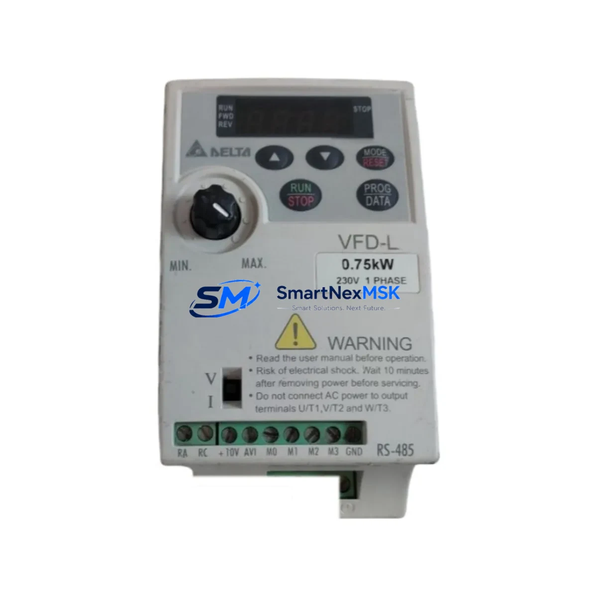
The Delta VFD007L21A is a 0.75 kW (1 HP) single-phase 200–240 V AC variable frequency drive from Delta Electronics’ VFD-L Series — one of the most widely deployed compact drive platforms in light industrial automation. As original VFD-L units approach end-of-life or become increasingly difficult to source, the VFD007L21A remains a proven retrofit-ready replacement that preserves existing wiring layouts, terminal assignments, and RS-485 Modbus RTU communication links without requiring PLC program rewrites or HMI screen redesigns.
Whether you are managing a scheduled control cabinet upgrade, responding to an unplanned drive failure, or executing a phased migration from legacy motion control to a modern automation architecture, the VFD007L21A provides a dimensionally compatible, electrically equivalent solution backed by a 12-month warranty and verified pre-shipment functional testing.
Upgrade Compatibility Table
| Parameter | VFD007L21A (This Unit) | Retrofit Notes |
|---|---|---|
| Power Rating | 0.75 kW / 1 HP | Matches legacy VFD-L 0.75 kW slot; verify motor nameplate FLA |
| Input Voltage | 1-Phase 200–240 V AC, 50/60 Hz | Confirm panel supply phase configuration before installation |
| Output Voltage | 3-Phase 200–240 V AC | Compatible with existing 3-phase motor wiring |
| Control Terminal Layout | Standard VFD-L terminal block (R/S, U/V/W, GND, +10V, ACM, FWD, REV, MI1–MI3, AVI, ACI, AFM) | Direct terminal-for-terminal rewire; no adapter required |
| Communication Protocol | RS-485 Modbus RTU | Retain existing PLC Modbus address; update baud rate if needed |
| Mounting / DIN Rail | Panel mount, compatible with standard DIN rail bracket | Footprint matches VFD-L enclosure cutout |
| Parameter Backup | Supported via Delta WPLSoft / DIADesigner or keypad copy | Back up original parameters before decommissioning old unit |
| HMI Compatibility | Delta DOP-B / DOP-E series via RS-485 | No HMI screen modification required if Modbus register map is unchanged |
| Warranty | 12 Months | Covers manufacturing defects; pre-shipment functional test included |
| Replacement Path | Direct drop-in for VFD007L21A, VFD004L21A (uprated), VFD002L21A (uprated) | Confirm motor load does not exceed drive rated current |
Retrofit Planning for Existing Automation Systems
A successful VFD007L21A retrofit begins well before the drive arrives on site. Start by auditing the existing control cabinet to document the full bill of materials: the outgoing drive’s terminal wiring diagram, the PLC I/O assignment sheet, and the HMI tag database. In most VFD-L installations, the host controller is a Delta DVP series PLC — commonly a DVP14SS2 or DVP32EH — communicating with the drive over an RS-485 link using the MODBUS RTU protocol at 9600 or 19200 baud. Confirm the Modbus station address (parameter P00.00 on the original unit) and replicate it on the VFD007L21A before powering the new drive.
On the power side, verify that the panel’s circuit breaker and input contactor are rated for the drive’s inrush current. The VFD007L21A draws approximately 5 A input current at full load; if the existing breaker is marginal, replace it with a correctly rated MCCB before commissioning. Check the EMC filter — many legacy VFD-L installations include a Delta DRF series line filter mounted upstream; this filter is fully compatible with the VFD007L21A and should be retained to suppress conducted emissions.
Terminal wiring on the VFD007L21A follows the standard VFD-L layout. The main power terminals (R, S for single-phase input; U, V, W for motor output) accept the same wire gauges as the original unit. Control terminals including FWD, REV, MI1 through MI3, AVI (0–10 V analog input), ACI (4–20 mA analog input), and AFM (analog frequency meter output) are pin-compatible. If the original installation used a Delta EMD-PG01L encoder feedback card or an EMD-BPS01 braking resistor module, verify that these accessories are mechanically compatible with the replacement unit’s option card slot before ordering.
For systems that include a Delta DOP-B07S411 or DOP-E series HMI panel, the existing Modbus register map for frequency setpoint (register 0x2001), output frequency (register 0x2103), and drive status word (register 0x2100) remains valid on the VFD007L21A. No HMI screen redraw is required. If the system uses a Delta IFD6500 USB-to-RS-485 converter for parameter upload and download, it is fully compatible with the VFD007L21A’s programming port.
Where the original installation includes a Delta DVP-EH3 expansion rack with additional analog I/O modules such as the DVP04AD or DVP02DA, confirm that the analog reference signal wiring to the drive’s AVI terminal is shielded and grounded at one end only to prevent ground loop interference — a common source of erratic speed reference in retrofit projects.
Downtime Control During System Migration
Minimizing production downtime during a VFD-L to VFD007L21A swap requires a structured hot-swap protocol. Begin by exporting the full parameter set from the original drive using the Delta WPLSoft parameter upload function or the drive’s built-in keypad copy feature (if a remote keypad such as the KPE-LE01 is installed). Store the parameter file with a timestamped filename and keep a printed copy in the control cabinet documentation folder.
Schedule the physical swap during a planned maintenance window. With the panel de-energized and LOTO procedures applied, disconnect the motor cables (U, V, W) first, then the input power (R, S), and finally the control wiring. Label every wire before removal. Install the VFD007L21A, reconnect control wiring terminal-for-terminal, then reconnect power. Before energizing, use a multimeter to verify that no control terminal is shorted to the PE (ground) rail — a common wiring error that can trigger an immediate fault on power-up.
On first power-up, navigate to parameter group P00 and confirm the motor nameplate data (rated voltage, rated current, rated frequency, rated speed) matches the connected motor. Run the drive in local keypad mode at 10 Hz for 30 seconds to verify motor rotation direction before switching to remote PLC control. Once the Modbus link is confirmed active (check the PLC’s communication status register), transfer control to the SCADA or HMI system and verify that the frequency setpoint, run/stop command, and fault status are all reading correctly. Total commissioning time for a prepared technician is typically under 45 minutes, keeping unplanned downtime to a minimum.
Retrofit Support FAQ
Q1: Is the VFD007L21A a direct drop-in replacement for my existing VFD-L Series drive?
Yes. The VFD007L21A is dimensionally and electrically compatible with other 0.75 kW VFD-L Series units. Terminal layout, mounting hole pattern, and Modbus register map are identical. You can reuse existing motor cables, control wiring, and PLC program without modification, provided the Modbus station address is set to match the original drive.
Q2: What pre-shipment testing is performed on each unit?
Every VFD007L21A shipped by SMARTNEXMSK undergoes a functional power-on test verifying input rectification, DC bus voltage, output PWM waveform, and control terminal response. Units are tested at rated voltage before packaging. A test report is available upon request. All units carry a 12-month warranty covering manufacturing defects from the date of shipment.
Q3: Can I use my existing RS-485 cable and Modbus configuration without changes?
In most cases, yes. The VFD007L21A supports RS-485 Modbus RTU at baud rates from 1200 to 38400 bps. Set parameter P09.01 (baud rate) and P09.04 (station address) to match your existing PLC configuration. If your PLC — such as a Delta DVP or Mitsubishi FX series — was previously communicating with the old drive at 9600 baud, simply replicate those settings on the new unit. No PLC ladder logic changes are required.
Q4: What should I do if the replacement drive triggers a fault immediately after wiring?
First, verify that input power phase (R, S) and motor output (U, V, W) terminals are not swapped. Check that no control terminal wire is shorted to PE. Confirm that the motor’s rated current does not exceed the drive’s output current rating (4.2 A for the VFD007L21A). If an OC (overcurrent) fault appears on first run, check for a short in the motor cable or a seized motor bearing. For OV (overvoltage) faults, verify that the input voltage is within the 200–240 V specification. Contact sales@smartnexmsk.com with the fault code and wiring diagram for rapid technical support.
© 2026 SMARTNEXMSK. All rights reserved.
Original Source: https://smartnexmsk.com
Contact: sales@smartnexmsk.com | +86 18259474341