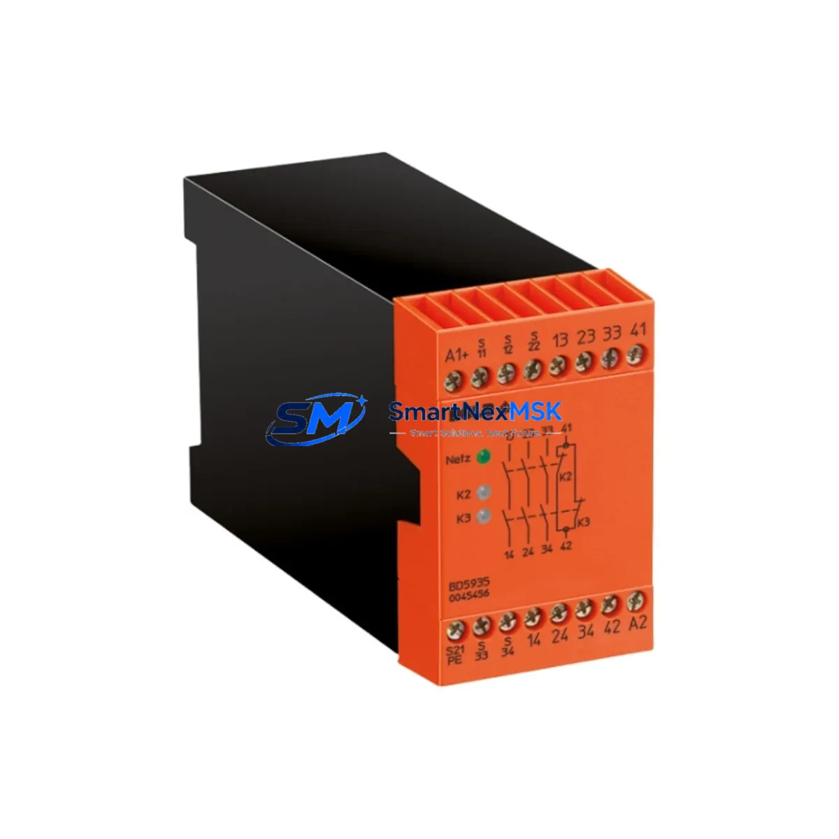
DOLD BD5935 Retrofit-Ready Safety Relay for SAFEMASTER Systems
The DOLD BD5935 is a proven, retrofit-ready safety relay module designed for seamless integration into SAFEMASTER safety control architectures. As legacy safety relay assemblies reach end-of-life or become increasingly difficult to source, the BD5935 provides a direct, wiring-compatible replacement path that preserves existing circuit logic, minimizes panel rework, and maintains SIL 2 / PLd functional safety compliance throughout the migration process. Whether you are upgrading an aging emergency stop loop, replacing a discontinued monitoring relay, or expanding a safety-rated I/O network, the BD5935 is engineered to slot into your existing control cabinet with minimal disruption.
Industrial facilities operating DOLD SAFEMASTER platforms — including lines built around the UH 6929, UH 6930, or BD 5980 series — frequently encounter the challenge of sourcing compatible replacement modules when original components are discontinued or no longer available through standard distribution channels. The BD5935 addresses this gap directly. Its terminal layout mirrors the standard DOLD 22.5 mm DIN-rail footprint, and its input circuit accepts both single-channel and dual-channel emergency stop configurations, making it compatible with a wide range of existing wiring schemes without requiring changes to the safety PLC program or HMI alarm mapping.
Upgrade Compatibility Table
| Parameter | BD5935 (This Unit) | Typical Legacy Replacement Target |
|---|---|---|
| Housing Width | 22.5 mm DIN-rail | 22.5 mm DIN-rail |
| Supply Voltage | 24 V DC / 115–230 V AC | 24 V DC / 115–230 V AC |
| Input Channels | Single / Dual Channel | Single / Dual Channel |
| Safety Output Contacts | 2 NO safety contacts | 2 NO safety contacts |
| Auxiliary Output | 1 NC diagnostic contact | 1 NC diagnostic contact |
| Safety Category | Cat. 4 / PLe / SIL 3 | Cat. 3–4 / PLd–PLe |
| Response Time | ≤ 20 ms | ≤ 25 ms |
| Terminal Compatibility | Screw terminals, 2.5 mm² | Screw terminals, 2.5 mm² |
| Communication | Standalone / hardwired | Standalone / hardwired |
| Replacement Recommendation | Direct drop-in for SAFEMASTER series | Verify dual-channel wiring polarity |
| Commissioning Note | Manual reset required after power-on | Check reset logic in safety PLC |
| Warranty | 12-Month Warranty — All units ship after full functional test | |
Retrofit Planning for Existing Automation Systems
A successful BD5935 retrofit begins well before the module arrives on-site. Engineers should start by auditing the existing safety circuit documentation, confirming the supply voltage rail feeding the relay (typically 24 V DC from a dedicated SITOP PSU8200 or equivalent safety-rated power supply), and verifying that the upstream safety PLC — commonly a Siemens S7-300 F-CPU or a Pilz PNOZmulti 2 controller — is configured to monitor the correct feedback loop signal from the relay’s NC auxiliary contact.
Terminal block wiring is the most critical step. On DOLD SAFEMASTER panels, the emergency stop input is typically wired to terminals A1/A2 (supply) and S11/S12 (channel 1) and S21/S22 (channel 2). Before removing the old relay, photograph and document all terminal connections. The BD5935 maintains the same terminal designation convention, so re-termination is straightforward, but technicians should use a calibrated torque screwdriver to achieve the specified 0.5–0.6 Nm clamping force on the 2.5 mm² conductors.
If the existing panel includes a DOLD BH 5928 or BH 5929 monitoring relay for guard door interlocking alongside the emergency stop circuit, both modules should be inspected during the same maintenance window. Similarly, if the safety architecture includes a UH 6929 speed monitoring relay for motor-driven axes, its feedback wiring to the safety PLC should be verified to ensure the BD5935 replacement does not inadvertently alter the overall safety function response time.
For panels integrating a Pilz PNOZ X3 or PNOZ X5 alongside DOLD modules, cross-reference the safety circuit category requirements. The BD5935 supports Category 4 / PLe, which meets or exceeds the requirements of most legacy Cat. 3 / PLd installations. Update the safety validation documentation accordingly and retain a copy for the machine technical file.
Where the control cabinet also houses a Siemens ET 200SP distributed I/O rack or a Phoenix Contact Inline safety I/O station, confirm that the BD5935’s output contacts are correctly mapped to the corresponding digital input channels. If the HMI — typically a Siemens TP700 Comfort or similar panel — displays a safety status screen, verify that the alarm tag linked to the relay feedback signal remains active after the swap. No PLC program changes are required if the terminal wiring and feedback loop are preserved, but a full safety function test must be performed before returning the machine to production.
Programming cable access (e.g., a Siemens 6ES7 972-0CB20-0XA0 MPI/PROFIBUS cable or a standard USB-to-RS485 adapter for Pilz systems) should be arranged in advance so that the safety PLC can be placed in test mode during commissioning without requiring a separate maintenance laptop to be sourced on short notice.
Downtime Control During System Migration
Minimizing unplanned downtime during a safety relay replacement requires a structured hot-swap protocol. Begin by scheduling the replacement during a planned maintenance window and notifying all relevant production supervisors. Before de-energizing the safety circuit, confirm that the safety PLC has been placed in maintenance mode and that all downstream actuators — servo drives, pneumatic valves, and conveyor motors — are in a safe, de-energized state.
Back up the current safety PLC program to an offline storage device before making any hardware changes. For Siemens F-CPU systems, use STEP 7 Safety or TIA Portal Safety to export the F-program and its safety signature. For Pilz PNOZmulti 2 systems, use PNOZmulti Configurator to save the current project file. This ensures that if any unexpected behavior occurs after the relay swap, the original program logic can be restored within minutes.
Once the BD5935 is installed and all terminals are re-torqued, perform a cold-start sequence: apply supply voltage, confirm the relay’s power LED illuminates, then actuate the emergency stop device and verify that the safety output contacts open within the specified response time. Release the emergency stop and perform a manual reset to confirm the relay latches correctly. Only after a successful reset-and-run cycle should the safety PLC be taken out of maintenance mode and the machine returned to automatic operation.
Keeping a spare BD5935 unit in the local maintenance store — alongside compatible spare parts such as a DOLD BH 5928 guard monitoring relay and a replacement SITOP power supply module — reduces the risk of extended downtime in the event of a future unplanned failure. All units supplied by SMARTNEXMSK are shipped after a full functional test and are covered by a 12-month warranty, providing additional assurance for critical production environments.
Retrofit Support FAQ
Q1: Is the BD5935 a direct replacement for my existing DOLD SAFEMASTER relay without rewiring?
A: In most SAFEMASTER installations, yes. The BD5935 uses the same 22.5 mm DIN-rail housing and identical terminal designations (A1/A2, S11/S12, S21/S22, 13/14, 23/24, 41/42). Verify your existing relay’s model number and wiring diagram before installation. If your legacy unit uses a different terminal layout, a wiring adapter may be required.
Q2: Do I need to modify my safety PLC program after replacing the relay?
A: No program changes are required if the terminal wiring and feedback loop signal are preserved. The BD5935’s NC auxiliary contact (terminals 41/42) provides the same feedback signal as the original relay. Perform a full safety function test after installation to confirm correct operation before resuming production.
Q3: What commissioning steps are required after installation?
A: After wiring, apply supply voltage and confirm the power LED is on. Actuate the emergency stop device to verify the safety outputs open. Release the E-stop and press the manual reset button to confirm the relay latches. Verify the safety PLC receives the correct feedback signal and clears any safety fault. Document the test results in the machine’s safety validation record.
Q4: What warranty and pre-shipment testing does SMARTNEXMSK provide?
A: Every BD5935 unit is functionally tested before shipment, including contact resistance verification, response time measurement, and reset-cycle confirmation. A 12-month warranty is provided from the date of shipment. Warranty claims are supported by our technical team at sales@smartnexmsk.com.
© 2026 SMARTNEXMSK. All rights reserved.
Original Source: https://smartnexmsk.com
Contact: sales@smartnexmsk.com | +86 18259474341