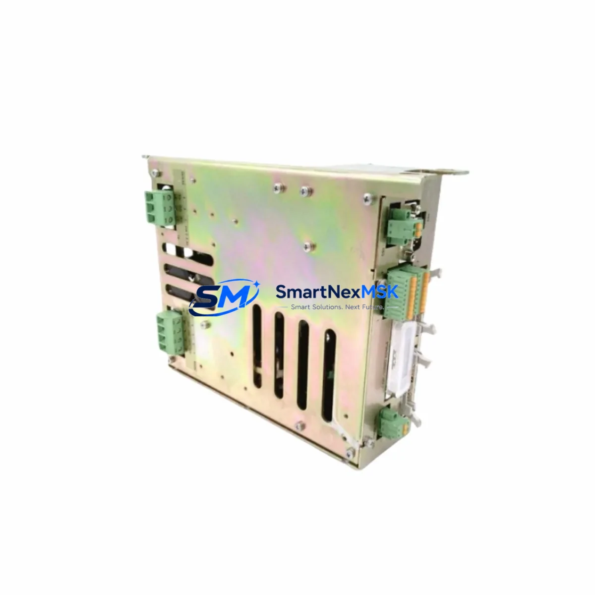
DUPLOMATIC DDC4-30-230/20 Retrofit-Ready AC Servo Drive for DDC4 Series Control Systems
The DUPLOMATIC DDC4-30-230/20 is a high-performance AC Servo Drive engineered for seamless integration into existing DDC4 Series control architectures. Whether you are replacing a failed unit on an active production line, upgrading an aging servo system, or executing a planned control cabinet modernization, the DDC4-30-230/20 delivers the electrical compatibility, communication protocol support, and mechanical form factor required for a smooth, low-risk retrofit. With verified compatibility across the DDC4 platform, this unit is a trusted choice for maintenance engineers and system integrators managing legacy automation assets.
Upgrade Compatibility Table
| Parameter | DDC4-30-230/20 Specification | Retrofit Notes |
|---|---|---|
| Input Voltage | 230 V AC, Single/Three Phase | Verify existing cabinet supply voltage before installation |
| Continuous Output Current | 30 A | Confirm motor nameplate current rating matches drive output |
| Communication Interface | Serial / Fieldbus (DDC4 native) | Compatible with existing DDC4 Series communication wiring; no protocol converter required |
| Mounting / Form Factor | Panel-mount, DIN-rail compatible | Direct mechanical replacement for DDC4 Series drives; verify backplane connector alignment |
| Terminal Wiring | Standard DDC4 terminal block layout | Map existing wiring diagram to new terminal designations before reconnection |
| Module Address | Configurable via parameter set | Restore original axis address from backup program or HMI configuration file |
| Program Compatibility | DDC4 Series PLC/motion program compatible | Upload original motion program; verify axis tuning parameters post-installation |
| HMI Screen Compatibility | Fully compatible with existing DDC4 HMI screens | No HMI screen redevelopment required for standard replacement |
| Warranty | 12-Month Warranty | Covers manufacturing defects; includes pre-shipment functional test report |
Retrofit Planning for Existing Automation Systems
A successful retrofit of the DDC4-30-230/20 begins well before the unit arrives on site. Engineers should start by auditing the existing control cabinet to confirm available power capacity. The cabinet power supply — often a DUPLOMATIC or third-party 24 V DC rail supply — must be verified to support the inrush and continuous current demands of the replacement drive. If the existing supply is marginal, upgrading to a higher-capacity unit before the servo drive swap will prevent nuisance tripping during commissioning.
Terminal wiring is the next critical checkpoint. The DDC4-30-230/20 uses the standard DDC4 Series terminal block layout, but engineers should cross-reference the original wiring diagram against the replacement unit’s terminal designations. Pay particular attention to the enable signal, fault relay output, encoder feedback connector, and motor power terminals. In many retrofit scenarios, the existing motor feedback cable — typically a DUPLOMATIC-compatible encoder cable assembly — can be reused without modification, significantly reducing rewiring time.
Backplane and rack interface compatibility should be confirmed for installations where the DDC4-30-230/20 is mounted within a multi-axis rack system. The DDC4 Series backplane connector is standardized across the product family, but physical inspection of the rack — including the DUPLOMATIC DDC4 rack chassis and any associated axis expansion slots — is recommended to rule out mechanical wear or connector damage on the rack side before inserting the replacement module.
Module address configuration is a frequently overlooked step. The DDC4-30-230/20 axis address must match the address stored in the PLC program and HMI configuration. Retrieve the original axis address from the machine’s electrical documentation or from the HMI project file. If the original address is unknown, it can often be recovered by reading the PLC program — typically developed on a DUPLOMATIC-compatible programming environment — before the failed drive is removed from service.
Communication link integrity should be verified after physical installation. The DDC4 Series uses a native serial or fieldbus communication link between the controller and the servo drives. After replacing the DDC4-30-230/20, confirm that the communication cable — whether RS-232, RS-485, or a proprietary DDC4 fieldbus cable — is properly seated and that the drive appears correctly on the network scan from the PLC or motion controller. If the system includes a DUPLOMATIC DDC4 motion controller or a third-party PLC with a DDC4-compatible communication module, a network diagnostic scan should be performed before enabling the axis.
I/O signal verification is the final pre-commissioning step. Confirm that all digital inputs — including the servo enable, home switch, overtravel limits, and external fault inputs — are correctly wired and logically active. Analog reference inputs, if used for speed or torque command, should be checked for correct scaling. Once all I/O signals are verified, the axis can be enabled in manual jog mode for initial motion testing before returning the machine to automatic cycle.
Downtime Control During System Migration
Minimizing production downtime during a DDC4-30-230/20 replacement requires a structured pre-outage preparation process. Before the scheduled maintenance window, engineers should complete a full backup of the PLC program, motion parameters, HMI project, and axis tuning data. This backup should be stored on a portable programming device — such as a laptop with the DUPLOMATIC DDC4 programming software installed — so that program restoration can begin immediately after the replacement drive is installed and powered.
The replacement unit should be pre-configured off-line where possible. Parameter sets, axis addresses, and communication settings can be loaded into the DDC4-30-230/20 before it is installed in the cabinet, reducing the time the machine is offline. Pre-shipment functional testing — included with every unit supplied by SMARTNEXMSK — confirms that the drive powers up correctly and responds to basic command inputs before it leaves the warehouse, eliminating the risk of receiving a non-functional unit during a critical maintenance window.
During the physical swap, label all wiring before disconnection and photograph the original terminal layout. This documentation protects against wiring errors during reconnection and provides a reference if the machine’s original electrical drawings are incomplete or outdated. After reconnection, perform a controlled power-up sequence: apply control power first, verify communication link establishment, then apply motor power and enable the axis in manual mode before returning to automatic operation. This staged power-up approach protects both the replacement drive and the connected servo motor from damage caused by wiring errors.
For multi-axis systems where the DDC4-30-230/20 is one of several drives on a shared rack or communication network, confirm that the remaining axes continue to operate correctly after the replacement. A brief automatic cycle test — running the machine through a representative production sequence at reduced speed — is the most reliable way to confirm that the retrofit has not introduced any unexpected interactions with adjacent axes or the overall control system.
Retrofit Support FAQ
Q: Is the DDC4-30-230/20 a direct drop-in replacement for my existing DDC4 Series servo drive?
A: Yes. The DDC4-30-230/20 is designed as a form-fit-function replacement within the DDC4 Series. The terminal layout, backplane connector, communication interface, and mounting dimensions are compatible with standard DDC4 Series installations. Minor parameter configuration — primarily axis address and tuning data restoration — is required after installation.
Q: What commissioning steps are required after installing the replacement drive?
A: After physical installation and wiring reconnection, restore the original axis address and parameter set from your backup. Verify the communication link from the PLC or motion controller, confirm all I/O signals are active and correctly mapped, then perform a manual jog test before returning the axis to automatic operation. Full commissioning typically takes 1–3 hours for a prepared engineer with access to the original machine documentation.
Q: Can I reuse my existing motor feedback cable and motor power cable?
A: In most cases, yes. The DDC4-30-230/20 uses standard DDC4 Series connector specifications for motor feedback and power connections. Inspect existing cables for insulation damage or connector wear before reuse. If the original encoder cable or motor power cable shows signs of degradation, replacement is recommended to avoid intermittent faults after the drive swap.
Q: What does the 12-month warranty cover, and is a test report included?
A: Every DDC4-30-230/20 supplied by SMARTNEXMSK includes a 12-month warranty covering manufacturing defects and functional failures under normal operating conditions. A pre-shipment functional test report is included with each unit, confirming that the drive has been powered up, communication-tested, and verified against DDC4 Series specifications before dispatch. Warranty claims are supported by our technical team at sales@smartnexmsk.com.
© 2026 SMARTNEXMSK. All rights reserved.
Original Source: https://smartnexmsk.com
Contact: sales@smartnexmsk.com | +86 18259474341