DYNAX AT200-LP Retrofit-Ready PLC Module for AT200 Series: Compatible Modernization & Smooth System Upgrade
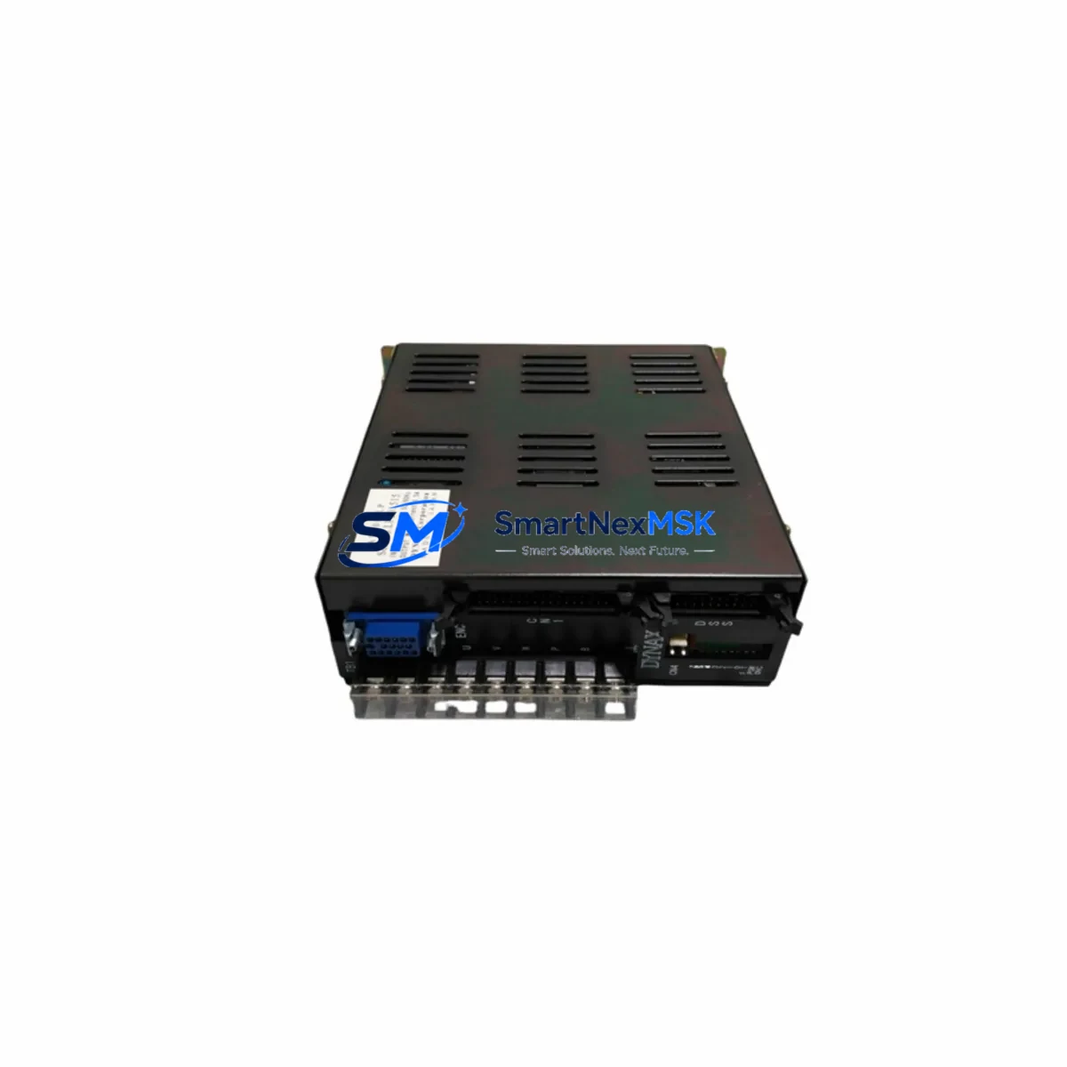
The DYNAX AT200-LP is a retrofit-ready programmable logic controller module engineered for seamless integration into existing AT200 Series control architectures. Whether you are replacing a discontinued unit, recovering a failed control cabinet, or executing a planned system modernization, the AT200-LP delivers verified drop-in compatibility with minimal engineering overhead. This module is purpose-built for industrial environments where downtime is costly and control continuity is non-negotiable.
Industrial facilities operating legacy DYNAX AT200 Series platforms frequently encounter the challenge of sourcing reliable replacement hardware as original components reach end-of-life. The AT200-LP addresses this directly by maintaining full backward compatibility with the AT200 Series backplane, preserving existing I/O addressing schemes and ladder logic programs without requiring wholesale reprogramming. Engineers responsible for maintaining aging production lines, packaging systems, material handling conveyors, and process control panels will find the AT200-LP a dependable solution that eliminates the risk of forced platform migration.
Upgrade Compatibility Table
| Parameter | Detail |
|---|---|
| Compatible Series | DYNAX AT200 Series |
| Replaced Model | AT200-LP (direct replacement) |
| Backplane Interface | AT200 Series standard backplane slot — no adapter required |
| Installation Type | DIN rail or panel-mount rack; standard AT200 chassis compatible |
| Communication Compatibility | RS-232, RS-485; Modbus RTU protocol retained |
| I/O Addressing | Existing I/O map preserved; no address reassignment required |
| Program Compatibility | Existing ladder logic transferable via AT200 programming cable |
| Power Supply Requirement | 24 VDC nominal; verify existing PSU capacity before installation |
| HMI Screen Compatibility | Compatible with AT200-linked HMI panels; screen tag remapping not required |
| Commissioning Requirement | Upload existing program, verify I/O scan, confirm comms link |
| Replacement Recommendation | Direct swap; retain original wiring harness and terminal blocks |
| Warranty | 12 Months from date of shipment |
Retrofit Planning for Existing Automation Systems
A successful AT200-LP retrofit begins well before the module arrives on-site. The first step is a thorough audit of the existing control cabinet, documenting the current AT200 Series rack configuration, the number of occupied backplane slots, and the power budget of the installed AT200 power supply module. In many legacy installations, the power supply module has been operating at or near its rated output for years; adding a replacement CPU module without verifying available headroom can introduce instability. Confirm that the supply can support the AT200-LP’s 24 VDC draw alongside any co-installed digital input modules, analog output modules, and communication interface modules already occupying the rack.
Terminal wiring is the next critical checkpoint. The AT200-LP uses the same terminal block layout as its predecessor, meaning field wiring — including sensor inputs, actuator outputs, and interlock circuits — can remain connected during the swap. However, it is good practice to photograph and document all terminal assignments before removing the old module. Pay particular attention to any shielded cable connections on analog channels and the grounding arrangement of the cabinet, as improper grounding can introduce noise on analog input modules and corrupt process variable readings.
For systems that include a DYNAX AT200 communication module handling Modbus RTU links to SCADA systems, energy meters, or variable frequency drives, verify that the baud rate, parity, and station address settings stored in the original module are documented before removal. The AT200-LP retains these parameters in non-volatile memory once programmed, but they must be re-entered if the module is installed fresh from stock. Similarly, if the control system interfaces with a DYNAX-compatible HMI panel via RS-232 or RS-485, confirm that the HMI communication driver settings match the AT200-LP’s port configuration to avoid screen communication faults after restart.
Program transfer is straightforward using the standard AT200 programming cable connected to a laptop running the AT200 programming software. Upload the existing program from the old module before removal if the module is still partially functional, or restore from the most recent backup file. After loading the program into the AT200-LP, perform a full I/O force test in stop mode to verify that each digital input module and digital output module responds correctly before returning the system to automatic operation. If the installation includes an AT200 expansion rack connected via the rack expansion cable, confirm that the expansion rack’s I/O modules are recognized correctly in the I/O configuration table.
Downtime Control During System Migration
Minimizing production downtime during an AT200-LP swap requires a structured pre-outage preparation protocol. Before scheduling the maintenance window, ensure the replacement AT200-LP has been bench-tested with a copy of the production program loaded and verified. This pre-commissioning step — sometimes called a factory acceptance test — confirms that the module powers up correctly, executes the program without faults, and communicates with a test HMI or programming terminal before it enters the plant.
During the outage window, follow a strict sequence: isolate the control cabinet from field power, document the current state of all output modules and interlock relays, remove the failed or end-of-life module, install the AT200-LP into the same backplane slot, restore field power, and upload the verified program. The entire physical swap typically takes under 30 minutes for a trained technician. The remaining time in the maintenance window should be allocated to I/O verification, communication link confirmation, and a supervised manual cycle of the controlled process before returning to full automatic mode.
Protecting the original program logic is paramount. Never overwrite the backup program file during the swap process. Maintain at least two copies of the program — one on the programming laptop and one on a USB drive stored separately — before beginning any hardware work. If the original AT200-LP module is still partially functional, perform a final program upload immediately before removal to capture any parameter changes made since the last scheduled backup. This discipline ensures that even in a worst-case scenario, the control logic can be fully restored without relying on memory or manual reconstruction.
Retrofit Support FAQ
Q1: Is the AT200-LP a direct drop-in replacement for the original DYNAX AT200-LP without any program modification?
Yes. The AT200-LP is designed as a direct replacement for the original AT200-LP within the AT200 Series platform. The backplane interface, I/O addressing, and communication port assignments are identical. Existing ladder logic programs can be loaded without modification. Minor parameter verification — such as communication baud rate and station address — is recommended as a standard commissioning step but does not require program editing.
Q2: What wiring changes are required when installing the AT200-LP into an existing AT200 Series cabinet?
No wiring changes are required. The AT200-LP uses the same terminal block layout and backplane connector as the original module. Field wiring, including sensor inputs, actuator outputs, and communication cables, can remain in place during the swap. It is recommended to verify terminal tightness and inspect for any signs of corrosion or insulation damage as part of the routine maintenance opportunity presented by the module replacement.
Q3: How is the AT200-LP tested before shipment, and what does the 12-month warranty cover?
Each AT200-LP unit undergoes functional testing prior to shipment, including power-on verification, I/O scan confirmation, and communication port check. The 12-month warranty covers manufacturing defects and functional failures under normal operating conditions. It does not cover damage resulting from incorrect installation, overvoltage, or environmental conditions outside the module’s rated specifications. Warranty claims are supported by our technical team with RMA processing and replacement dispatch.
Q4: Can the AT200-LP be used in a system that also includes third-party I/O modules or communication gateways not originally from DYNAX?
The AT200-LP communicates via standard Modbus RTU over RS-485, which is widely supported by third-party I/O expansion modules, communication gateways, and SCADA interface devices. Compatibility with specific third-party devices should be verified against the AT200-LP’s communication specification sheet. Our technical support team can assist with protocol configuration guidance for common integration scenarios involving non-DYNAX peripheral devices.
© 2026 SMARTNEXMSK. All rights reserved.
Original Source: https://smartnexmsk.com
Contact: sales@smartnexmsk.com | +86 18259474341