E-T-A 2210-S211-P1F2-H111-4A Maintenance-Ready Spare 2210: Spare Parts Replacement & Industrial Downtime Risk Control
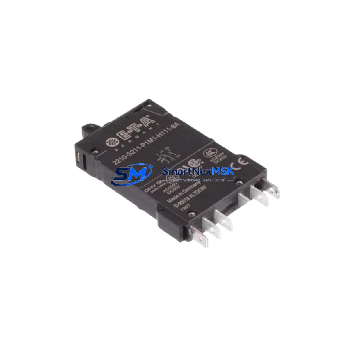
The E-T-A 2210-S211-P1F2-H111-4A is a single-pole, 4A thermal circuit breaker from E-T-A’s proven 2210 Series, engineered for panel-mount installation in industrial control cabinets, PLC enclosures, and DCS power distribution assemblies. Designed and manufactured in Germany, this component delivers reliable overcurrent and short-circuit protection for branch circuits in demanding automation environments — from discrete manufacturing lines to process control systems operating 24/7.
For maintenance engineers managing aging control systems, the 2210-S211-P1F2-H111-4A represents a critical line-replaceable unit (LRU). Its compact footprint, snap-in panel mounting, and standardized terminal pitch make it a direct fit for legacy and current-generation control cabinets without rewiring. Procurement engineers can source this part as a certified original spare, backed by a 12-month warranty and pre-shipment electrical testing, ensuring that emergency replacements arrive ready to install.
Spare Maintenance Table
| Parameter | Specification |
|---|---|
| Part Number / SKU | 2210-S211-P1F2-H111-4A |
| Brand | E-T-A (Elektro-Thermische Auslöser GmbH) |
| Series | 2210 |
| Product Type | Thermal Circuit Breaker, Single-Pole |
| Rated Current | 4A |
| Poles | 1-Pole |
| Trip Characteristic | Thermal (slow-blow, overload protection) |
| Mounting Style | Panel Mount (snap-in) |
| Actuator Type | Push-button reset (manual) |
| Rated Voltage (AC) | Up to 250V AC |
| Rated Voltage (DC) | Up to 65V DC |
| Breaking Capacity | 1,500A (at rated voltage) |
| Operating Temperature | -25°C to +85°C |
| Country of Origin | Germany (DE) |
| Compatibility | Direct replacement for E-T-A 2210 Series variants; compatible with standard 22mm panel cutouts |
| Installation | Snap-in panel mount; screw terminal connections |
| Application Environment | Industrial control cabinets, PLC enclosures, DCS panels, MCC assemblies |
| Maintenance Recommendation | Inspect annually; replace immediately upon nuisance tripping or visible contact wear |
| Warranty | 12 Months — includes pre-shipment electrical test and functional verification |
Maintenance Planning for Continuous Operation
When the 2210-S211-P1F2-H111-4A is flagged during a scheduled control cabinet inspection or trips unexpectedly during production, the replacement event should trigger a broader review of the surrounding electrical circuit. Experienced maintenance engineers know that a thermal circuit breaker rarely fails in isolation — the root cause is often upstream or downstream of the breaker itself.
Begin by verifying the 24VDC or 120VAC power supply module feeding the branch circuit. A degraded power supply with excessive ripple or voltage sag can cause nuisance tripping of thermal breakers even when the load is within spec. If the cabinet uses a SITOP PSU8200 or equivalent DIN-rail power supply, check its output voltage and current capacity before installing the replacement breaker.
Next, inspect the terminal blocks and wiring harness connected to the breaker’s output. Loose screw terminals, corroded ferrules, or undersized conductors create localized resistance that generates heat — accelerating thermal element fatigue. Phoenix Contact or Weidmüller terminal blocks in the same row should be torqued to spec and visually inspected for discoloration.
For PLC-controlled systems, confirm that the I/O module or relay output card downstream of the breaker is not drawing excessive inrush current. Solid-state relay (SSR) modules and digital output cards with capacitive loads can produce current spikes that stress thermal breakers. If the circuit drives a 24VDC relay module or a bank of solenoid valves, verify the total inrush current against the breaker’s time-current characteristic curve.
In DCS and safety-instrumented systems, the branch protected by the 2210-S211-P1F2-H111-4A may supply a signal isolator, loop-powered transmitter, or intrinsic safety barrier. These devices are sensitive to supply interruptions — a tripped breaker can cause a process upset or spurious safety trip. Maintain at least one spare 2210 Series breaker per control cabinet to enable immediate swap-out without waiting for procurement.
During planned shutdowns, also inspect the backplane bus connectors and communication module power rails in the same cabinet. PROFIBUS DP repeaters, PROFINET switches, and Modbus RTU converters often share the same power distribution bus as the breaker circuit. A loose backplane connector or failing bus terminator can cause intermittent faults that are misdiagnosed as breaker failures.
Finally, review the fuse holders and miniature fuses in the same distribution row. Blown fuses adjacent to a tripped circuit breaker indicate a systemic overload condition that must be resolved before the replacement breaker is energized. Stocking a mixed spare kit — including the 2210-S211-P1F2-H111-4A, compatible fuse links, and a spare relay output module — is the most effective strategy for minimizing mean time to repair (MTTR) in high-availability automation environments.
Site Replacement Workflow
Step 1 — Isolation & Lockout/Tagout (LOTO): De-energize the affected branch circuit and apply LOTO per site safety procedures. Confirm zero voltage at the breaker terminals with a calibrated multimeter before proceeding.
Step 2 — Document the existing configuration: Photograph the breaker position, terminal wiring, and adjacent labels. Note the original part number (2210-S211-P1F2-H111-4A) and any site-specific cable tags for traceability.
Step 3 — Remove the failed unit: Release the snap-in panel clip and disconnect the screw terminals. Retain the failed unit for failure analysis if required by your maintenance management system (CMMS).
Step 4 — Install the replacement: Snap the new 2210-S211-P1F2-H111-4A into the panel cutout. Reconnect terminals to the documented torque specification. Verify that the push-button actuator is in the reset (ON) position before energizing.
Step 5 — Functional verification: Re-energize the branch circuit and confirm normal operation of the downstream load — PLC I/O card, relay module, signal isolator, or HMI power supply. Log the replacement in your CMMS with the date, technician ID, and new part serial number.
Step 6 — Replenish spare stock: Immediately reorder the consumed spare to maintain your minimum stock level. The 2210 Series is a long-lifecycle product, but lead times for original E-T-A components can vary — maintaining a buffer of 2–3 units per active cabinet type is recommended for critical production lines.
Spare Parts Support FAQ
Q1: Is the 2210-S211-P1F2-H111-4A a direct drop-in replacement for other 2210 Series variants?
The 2210 Series uses a standardized panel-mount footprint, so most 2210 variants share the same cutout dimensions and terminal pitch. However, the rated current (4A in this case) and trip characteristic must match the original circuit design. Always verify the current rating and actuator type (push-button vs. toggle) before substituting a different 2210 variant. If you are replacing a 2A or 6A variant, the 2210-S211-P1F2-H111-4A is not a direct electrical substitute — contact our technical team for guidance.
Q2: How is the part tested before shipment?
Every 2210-S211-P1F2-H111-4A unit undergoes pre-shipment electrical verification, including continuity check, trip current test, and visual inspection for contact integrity and actuator function. Units that fail any test parameter are quarantined and not shipped. A test report is available upon request for critical applications.
Q3: What is the recommended spare parts stocking strategy for the 2210 Series?
For production environments with multiple control cabinets, we recommend maintaining a minimum of 2–3 units of each active 2210 Series variant on-site. Group your spare inventory by current rating (2A, 4A, 6A, 10A) and store in a labeled, ESD-safe cabinet. Conduct a spare parts audit annually aligned with your planned maintenance schedule to identify consumed or expired stock.
Q4: What does the 12-month warranty cover?
The 12-month warranty covers manufacturing defects, premature trip failure under rated conditions, and contact welding or mechanical actuator failure under normal operating loads. It does not cover damage caused by installation errors, overcurrent events exceeding the rated breaking capacity, or environmental exposure beyond the specified operating temperature range. Warranty claims are processed with photographic evidence and a completed failure report form.
© 2026 SMARTNEXMSK. All rights reserved.
Original Source: https://smartnexmsk.com
Contact: sales@smartnexmsk.com | +86 18259474341