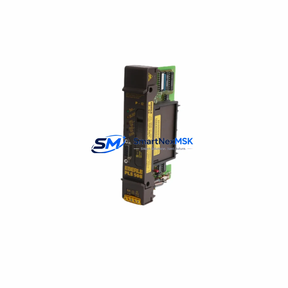
EBERLE PLS 508 P-82 Maintenance-Ready Spare for PLS 500 Series Automation
The EBERLE PLS 508 P-82 is a critical programmable logic controller module within the PLS 500 Series, widely deployed in industrial process control, machine automation, and building management systems across European and global manufacturing facilities. When this module fails or reaches end-of-service life, unplanned downtime can cascade across entire production lines. Sourcing a verified, original-specification spare is the fastest path to restoring system integrity without compromising control logic or I/O mapping.
At SMARTNEXMSK, every PLS 508 P-82 unit is sourced from authorized supply chains, inspected against original EBERLE electrical specifications, and tested under load conditions before shipment. Our 12-month warranty covers functional defects under normal operating conditions, giving maintenance engineers and procurement teams the confidence to stock this module as a long-term spare.
Whether you are managing a planned shutdown, responding to an emergency fault, or building a preventive maintenance inventory, the PLS 508 P-82 is available for immediate dispatch with full documentation support.
Spare Maintenance Table
| Part Number / SKU | PLS 508 P-82 |
| Brand | EBERLE |
| Compatible Series | PLS 500 Series |
| Module Type | Programmable Logic Controller (PLC) Module |
| Country of Origin | Germany |
| Supply Voltage | Per PLS 500 Series specification (24 VDC nominal, verify with system datasheet) |
| Operating Temperature | 0°C to +55°C (standard industrial range) |
| Mounting | DIN rail / backplane slot per PLS 500 rack configuration |
| Communication Interface | Compatible with PLS 500 Series backplane bus |
| Compatibility Verification | Cross-referenced against PLS 500 Series hardware manual prior to shipment |
| Pre-Shipment Testing | Functional load test performed on every unit |
| Warranty | 12 Months — covers functional defects under normal operating conditions |
| Typical Application | Process control, machine automation, HVAC/BMS, legacy system life extension |
| Condition | Original spare — new or fully refurbished to OEM specification |
| Lead Time | In stock — same-day or next-business-day dispatch available |
Maintenance Planning for Continuous Operation
Replacing the PLS 508 P-82 in a live PLS 500 control cabinet is rarely an isolated task. Experienced maintenance engineers know that a module fault often signals stress across adjacent components in the same electrical circuit. Before returning the system to service, a thorough inspection of the following components is strongly recommended:
Power Supply Module: The PLS 500 Series rack relies on a dedicated 24 VDC power supply module to feed the CPU and I/O backplane. Voltage ripple or supply degradation is a common root cause of PLC module faults. Verify output voltage stability under load before installing the replacement PLS 508 P-82.
I/O Expansion Modules: Digital and analog I/O modules connected to the same backplane should be inspected for address conflicts, blown fuses on output channels, and signal integrity. EBERLE PLS 500 Series I/O modules share the backplane bus with the CPU module — a shorted output card can cause upstream CPU faults.
Communication Module / Network Interface: If the PLS 500 system communicates via Profibus, Modbus RTU, or a proprietary EBERLE network, the communication module should be checked for firmware version compatibility with the replacement CPU. Mismatched firmware between the CPU and communication card is a known source of post-replacement communication faults.
Terminal Blocks and Field Wiring: Loose or corroded terminal connections on the I/O wiring side are a frequent cause of intermittent faults that are incorrectly attributed to the PLC module itself. Inspect all terminal blocks, especially in high-vibration or high-humidity environments, and re-torque connections to specification.
Relay Output Modules: Relay output cards in the same cabinet should be checked for contact wear, especially if the PLS 508 P-82 was controlling inductive loads such as motor contactors or solenoid valves. Worn relay contacts can generate voltage spikes that damage the CPU module over time.
Signal Isolators and Barriers: Analog input channels connected to field transmitters often pass through signal isolators or Zener barriers. These components should be tested for correct output range and isolation resistance, particularly in hazardous area installations.
Fuses and Circuit Protection: Check all fuse holders on the 24 VDC distribution rail within the control cabinet. A blown fuse on the CPU supply rail is sometimes the primary fault, not the module itself. Replace any fuses that show signs of heat discoloration or intermittent continuity.
HMI / Operator Panel: If the PLS 500 system is connected to an EBERLE or third-party HMI panel, verify that the HMI communication link is restored after module replacement. Some HMI configurations store the PLC IP address or node address locally and may require reconfiguration after a CPU swap.
Battery / Memory Backup: PLS 500 Series CPU modules typically include an onboard lithium battery for program and data retention during power loss. When installing a replacement PLS 508 P-82, confirm the battery voltage is within specification and replace it as part of the maintenance event to avoid program loss during the next power cycle.
Stocking the PLS 508 P-82 alongside these associated components — power supply module, I/O cards, communication module, and relay output cards — as a coordinated spare kit significantly reduces mean time to repair (MTTR) and eliminates secondary sourcing delays during emergency shutdowns.
Site Replacement Workflow
Step 1 — Fault Isolation: Before removing the PLS 508 P-82, document all active fault codes from the HMI or programming terminal. Capture a screenshot or printout of the current I/O status table. This baseline is essential for post-replacement verification.
Step 2 — Safe Isolation: De-energize the control cabinet following your site LOTO (Lockout/Tagout) procedure. Confirm that the 24 VDC supply rail is de-energized with a calibrated multimeter before touching any backplane components.
Step 3 — Module Removal: Release the PLS 508 P-82 from the backplane slot using the module ejector lever. Note the slot position and any DIP switch or jumper settings on the outgoing module — these must be replicated on the replacement unit.
Step 4 — Replacement Installation: Insert the new PLS 508 P-82 into the correct backplane slot. Confirm the module is fully seated and the locking tab is engaged. Replicate all DIP switch and jumper settings from the original module.
Step 5 — Program Restore: If the replacement module does not retain the original program (new unit), connect the programming terminal and download the latest verified program version from your backup archive. Never commission a replacement PLC module without a confirmed program backup.
Step 6 — Power-Up and Verification: Re-energize the cabinet and observe the module status LEDs. Confirm that all I/O channels report correctly on the HMI. Run a functional test of all controlled outputs before returning the system to automatic mode.
Step 7 — Documentation: Record the replacement event in your maintenance management system (CMMS), including the date, replaced module serial number, technician name, and post-replacement test results. Update your spare parts inventory to trigger reorder of the consumed PLS 508 P-82 unit.
Spare Parts Support FAQ
Q1: Is the PLS 508 P-82 a direct drop-in replacement for the original EBERLE module in a PLS 500 rack?
Yes. The PLS 508 P-82 is designed to fit the PLS 500 Series backplane slot and is compatible with the original hardware and software architecture of the PLS 500 system. However, we recommend verifying the hardware revision of your existing rack against the replacement module’s revision marking before installation, as minor hardware revisions may affect firmware compatibility.
Q2: What does the 12-month warranty cover, and how is a warranty claim processed?
The 12-month warranty covers functional defects arising under normal operating conditions — correct supply voltage, within-specification ambient temperature, and proper installation. It does not cover damage caused by incorrect wiring, overvoltage events, or physical impact. To initiate a warranty claim, contact sales@smartnexmsk.com with the order number, fault description, and photos of the installed module. We will arrange return shipping and replacement or repair within an agreed timeframe.
Q3: How do you verify compatibility before shipment, and what documentation is provided?
Every PLS 508 P-82 unit is cross-referenced against the EBERLE PLS 500 Series hardware manual and tested under functional load conditions before dispatch. We provide a test report and, where available, the original manufacturer datasheet. If your application requires specific firmware version matching or hardware revision confirmation, please provide your existing module’s nameplate data at the time of order so we can verify compatibility before shipment.
Q4: Can you support long-term or blanket purchase orders for ongoing maintenance programs?
Yes. SMARTNEXMSK supports long-term supply agreements for maintenance teams managing aging PLS 500 installations. We can reserve stock, provide scheduled delivery, and offer volume pricing for multi-unit orders. Contact sales@smartnexmsk.com or call +86 18259474341 to discuss your maintenance program requirements.
© 2026 SMARTNEXMSK. All rights reserved.
Original Source: https://smartnexmsk.com
Contact: sales@smartnexmsk.com | +86 18259474341