EMG IDC32-1.1 Retrofit-Ready Drive Control Board for IDC Series: Compatible Modernization & Smooth Legacy System Upgrade
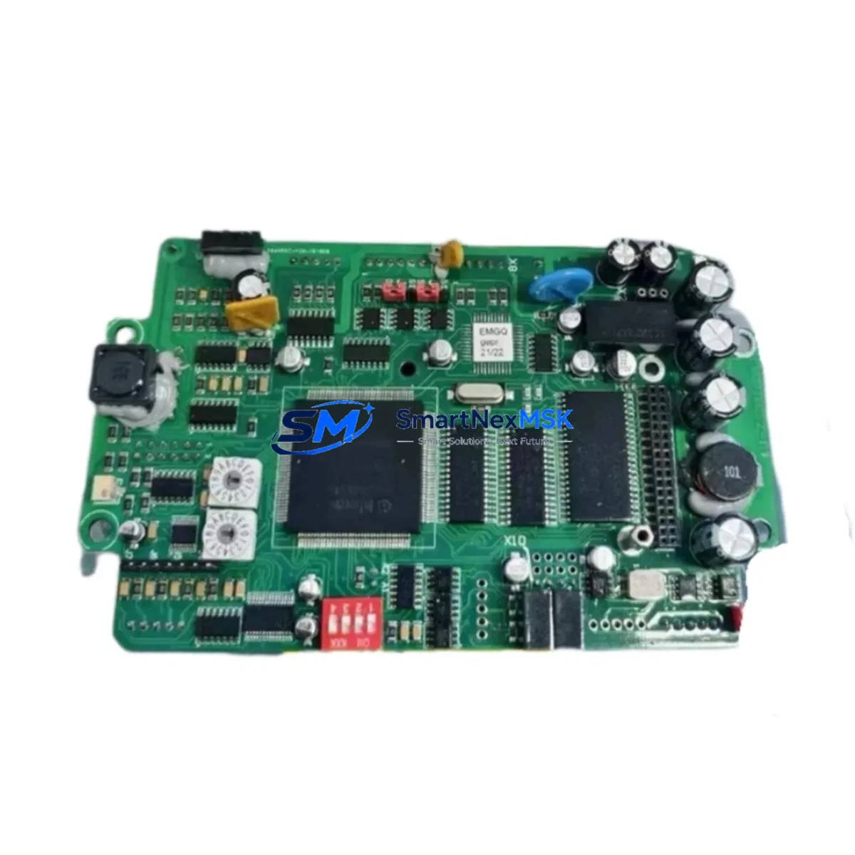
The EMG IDC32-1.1 is a retrofit-ready drive control board engineered for direct replacement and system modernization within the EMG IDC Series drive platform. As legacy IDC Series drives reach end-of-life and original spare parts become increasingly scarce, the IDC32-1.1 provides a verified, drop-in compatible solution that allows maintenance engineers and system integrators to restore full drive functionality without redesigning the control cabinet or rewriting existing PLC programs.
Whether you are managing a planned upgrade cycle, responding to an unplanned drive failure, or executing a phased modernization of an older production line, the IDC32-1.1 is designed to minimize engineering effort and reduce total downtime. Each unit is pre-tested against IDC Series electrical and communication specifications before shipment, and is backed by a 12-month warranty covering manufacturing defects and functional performance.
Upgrade Compatibility Table
| Parameter | Details |
|---|---|
| Compatible Series | EMG IDC Series (IDC32 platform) |
| Replaces / Upgrades | IDC32-1.0, IDC32-1.1 (original), IDC32 legacy control boards |
| Mounting Interface | Standard IDC Series backplane slot; no mechanical modification required |
| Terminal Wiring | Compatible with existing IDC Series terminal block layouts; verify pin assignments against original wiring diagram before installation |
| Communication Compatibility | Supports IDC Series native communication protocols; verify fieldbus configuration (e.g., PROFIBUS, CANopen) matches existing network setup |
| Power Supply Requirement | Confirm available power capacity from existing IDC Series power supply module before installation |
| Replacement Recommendation | Direct drop-in for IDC32-1.1; review firmware version compatibility for IDC32-1.0 installations |
| Commissioning Notes | Re-verify module address settings, I/O mapping, and HMI screen parameter bindings after board swap |
| Warranty | 12 months from date of shipment; covers manufacturing defects and functional performance |
Retrofit Planning for Existing Automation Systems
A successful IDC32-1.1 retrofit begins well before the physical board swap. Engineers working on legacy IDC Series installations should start by auditing the full control cabinet configuration. This typically includes documenting the existing IDC Series power supply module capacity to confirm it can support the replacement board’s operating current draw, and verifying that the IDC Series backplane or rack assembly is in serviceable condition with no damaged slot connectors or corroded bus contacts.
Terminal wiring is one of the most common sources of commissioning delays during drive control board replacements. Before removing the original board, photograph and document all terminal connections. Cross-reference against the original IDC Series wiring diagram, paying particular attention to analog reference inputs, digital I/O assignments, and any external feedback signals from encoders or tachometers. If the installation includes an IDC Series I/O expansion module, confirm that the expansion module’s address settings are recorded and will be re-applied correctly after the board swap.
For systems integrated with a higher-level PLC — such as a Siemens S7-300 or S7-400 CPU module communicating over PROFIBUS-DP — verify that the GSD file and hardware configuration in the PLC project still match the IDC32-1.1’s device profile. In installations where the drive communicates via CANopen, confirm node ID settings and baud rate configuration before powering up the replacement board. If the site uses a PROFIBUS repeater or CANopen gateway module to bridge the drive network to the main control network, these devices should be checked for correct termination and address settings as part of the pre-commissioning checklist.
HMI integration is another area requiring careful attention. If the production line uses a Siemens TP or MP series HMI panel — or an equivalent operator interface — bound to IDC Series drive parameters, verify that all screen objects referencing drive status words, speed setpoints, and fault codes remain correctly mapped after the board replacement. Parameter address offsets can shift between firmware revisions, so a full HMI screen validation pass is recommended before returning the line to production.
Finally, if the control cabinet includes a Siemens ET 200 distributed I/O station or similar remote I/O system connected to the same PROFIBUS segment as the IDC drive, confirm that the network scan and device recognition sequence completes correctly after the IDC32-1.1 is installed. This is particularly important in multi-drive cabinets where several IDC Series drives share a common fieldbus segment managed by a central CP 342-5 or CP 443-5 communications processor.
Downtime Control During System Migration
Minimizing unplanned downtime is the primary operational concern when replacing a drive control board in a running production environment. The IDC32-1.1 is designed to support a structured, low-risk swap procedure that protects existing program logic and maintains field control continuity.
Before initiating the replacement, back up the full drive parameter set using the available programming interface or parameter upload tool. If the original IDC32-1.1 is still partially functional, perform a complete parameter upload to a laptop or handheld programmer before powering down. This ensures that motor data, ramp settings, PID configurations, and fieldbus node assignments can be restored to the replacement board without manual re-entry.
During the physical swap, follow a controlled power-down sequence: isolate the drive from the main power bus, discharge DC link capacitors per the IDC Series service manual, and only then remove the control board. Install the replacement IDC32-1.1, restore all terminal connections per the documented wiring layout, and verify module address switches match the original configuration before applying power.
On first power-up, perform a controlled no-load test before reconnecting the motor load. Verify that the drive recognizes the motor data, that all I/O signals respond correctly, and that the fieldbus communication link re-establishes without errors. Only after a successful no-load verification should the motor load be reconnected and a supervised test run performed at reduced speed before returning to full production speed.
This structured approach — parameter backup, controlled swap, no-load verification, supervised test run — consistently delivers the shortest possible return-to-production time while protecting the integrity of the existing control program and field wiring.
Retrofit Support FAQ
Q: Is the IDC32-1.1 a direct drop-in replacement for the original IDC32-1.1 board?
A: Yes. The IDC32-1.1 is designed as a direct functional replacement for the original EMG IDC32-1.1 drive control board. Mechanical mounting, backplane interface, and terminal wiring layouts are compatible. We recommend verifying firmware version compatibility if replacing an IDC32-1.0 board, as minor parameter address differences may apply.
Q: What pre-shipment testing is performed on each unit?
A: Every IDC32-1.1 unit undergoes functional testing against IDC Series electrical specifications before shipment. Test records are available upon request. Each unit is shipped with a 12-month warranty covering manufacturing defects and verified functional performance.
Q: What should I check regarding terminal wiring and I/O compatibility before installation?
A: Document all existing terminal connections before removing the original board. Cross-reference against the IDC Series wiring diagram for your specific installation. Pay particular attention to analog input scaling, digital I/O polarity, and any external feedback device wiring. If an I/O expansion module is present, record its address settings before the swap.
Q: How do I verify communication link compatibility with my existing PLC or fieldbus network?
A: Confirm that the IDC32-1.1’s fieldbus node address, baud rate, and protocol settings match the original board’s configuration. For PROFIBUS-DP installations, verify the GSD file version in your PLC hardware configuration. For CANopen networks, confirm node ID and heartbeat settings. Re-establish and verify the communication link during the no-load commissioning phase before reconnecting the motor load.
© 2026 SMARTNEXMSK. All rights reserved.
Original Source: https://smartnexmsk.com
Contact: sales@smartnexmsk.com | +86 18259474341