ENTEK EY-6691 SETX2 Retrofit-Ready Relay Card for EY Series Control Systems
The ENTEK EY-6691 SETX2 is a supply relay card engineered for seamless integration into legacy EY Series vibration monitoring systems. As aging machinery protection platforms approach end-of-life or face discontinued spare-parts availability, the EY-6691 SETX2 provides a validated, drop-in retrofit path that preserves existing wiring infrastructure, minimizes engineering rework, and restores full system functionality without requiring a complete platform overhaul. Whether you are replacing a failed card in a running plant or proactively upgrading a critical protection loop, this module delivers the reliability and compatibility that industrial maintenance teams demand.
ENTEK’s EY Series platform has been widely deployed across rotating machinery protection applications including turbines, compressors, pumps, and fans. The EY-6691 SETX2 relay card occupies the same backplane slot as its predecessors, maintaining physical and electrical compatibility with the EY Series rack chassis. Terminal wiring assignments are preserved, eliminating the need to re-label or re-route field cables during the swap. This is a critical advantage in live-plant environments where minimizing intervention scope directly controls risk.
Upgrade Compatibility Table
| Parameter | Detail |
|---|---|
| SKU / Part Number | EY-6691 SETX2 |
| Brand | ENTEK |
| Compatible Series | ENTEK EY Series Vibration Monitoring Systems |
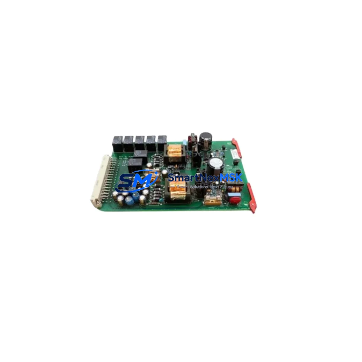
| Module Function | Supply Relay Card — setpoint output relay switching |
| Backplane Interface | EY Series rack-compatible edge connector; direct slot replacement |
| Terminal Wiring | Pin-compatible with existing EY Series field wiring; no re-termination required |
| Communication Compatibility | Operates within EY Series internal bus architecture; no protocol reconfiguration needed |
| Installation Requirement | Power-down rack before card swap; verify rack address DIP switch settings match original card |
| Replacement Recommendation | Direct replacement for failed or end-of-life EY Series relay output cards |
| Commissioning Focus | Verify relay setpoint thresholds, energize/de-energize logic, and alarm trip outputs post-installation |
| Warranty | 12-Month Warranty — covers manufacturing defects and functional failure under normal operating conditions |
| Origin | USA (ENTEK IRD Mechanalysis) |
| Stock Status | In Stock — available for immediate dispatch |
Retrofit Planning for Existing Automation Systems
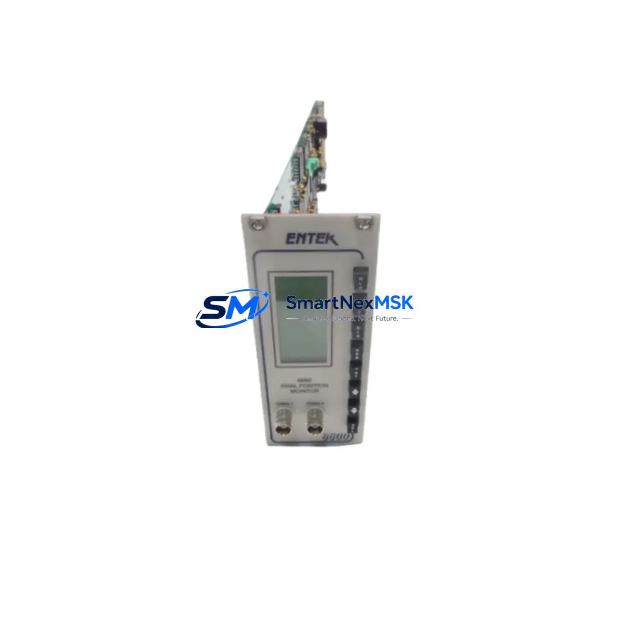
Successful integration of the EY-6691 SETX2 into an existing protection system begins well before the card arrives on-site. Maintenance engineers should first audit the full EY Series rack assembly to document which slots are occupied and which modules are active. A typical EY Series cabinet may house an ENTEK EY-6600 monitor chassis alongside multiple signal conditioning cards, a dedicated EY-6610 power supply module, and one or more EY-6620 transducer input cards handling proximity probe or accelerometer signals from the machine train. Understanding the full rack population ensures that the relay card replacement does not inadvertently disturb adjacent module addressing or shared power rails.
Before removing the original relay card, engineers should capture the existing DIP switch configuration for module address and relay logic polarity. The EY-6691 SETX2 must be configured to match these settings exactly to avoid alarm logic inversion or missed trip conditions after reinsertion. If the plant uses an ENTEK EY-6680 communication interface card for Modbus or serial data acquisition to a supervisory SCADA or DCS, confirm that the relay card’s output assignments are correctly mapped in the host system’s I/O database before going live.
For sites migrating from older ENTEK IRD-era hardware to the EY Series platform, the EY-6691 SETX2 often serves as the relay output layer in a broader upgrade that may also involve replacing legacy IRD 890 or IRD 970 monitor cards with EY Series equivalents. In these scenarios, the relay card must be validated against the new monitor card’s trip output voltage and contact rating to ensure compatibility with existing shutdown interlock circuits. Where the plant uses a Bently Nevada 3500 or Emerson CSI 6500 system in parallel for cross-validation, relay output timing and logic should be verified against both platforms before returning the machine to service.
Power budget verification is essential. The EY Series rack power supply — typically an EY-6610 or equivalent — must have sufficient headroom to support the EY-6691 SETX2’s relay coil current draw alongside all other installed cards. If the rack is near capacity, a power audit should be completed before installation. Terminal block torque specifications should be followed during any re-termination work, and all field wiring should be inspected for insulation integrity before energizing the rack.
Downtime Control During System Migration
Minimizing unplanned downtime is the primary operational concern when replacing a relay card in a live machinery protection system. The recommended approach is to pre-configure the EY-6691 SETX2 on the bench before the maintenance window opens. This includes setting all DIP switches to match the original card’s address and logic configuration, performing a bench-level continuity check on relay contacts, and verifying that the card powers up correctly in a test rack if one is available.
During the swap window, the sequence should follow a defined isolation procedure: notify the control room, inhibit the relevant protection channel in the monitoring system to prevent spurious trips during card removal, extract the failed card, insert the EY-6691 SETX2, and restore the inhibit before re-energizing. This sequence protects the original program logic in the host DCS or safety PLC — whether that is a Rockwell Automation ControlLogix, a Siemens S7-400H, or a dedicated safety controller — from receiving false trip signals during the transition.
After reinsertion, the commissioning checklist should confirm: relay setpoint thresholds match the original alarm and trip levels; relay energize/de-energize behavior is correct for the application (normally energized or normally de-energized); HMI alarm displays on the operator workstation reflect the correct channel status; and any Modbus register mappings for the relay output channel are returning valid data to the SCADA host. A functional trip test — using a calibrated signal source to drive the monitor channel above the trip setpoint — should be performed before releasing the machine back to normal operation. All test results should be documented in the plant’s maintenance management system for audit trail purposes.
Retrofit Support FAQ
Q1: Is the EY-6691 SETX2 a direct replacement for all EY Series relay output cards?
The EY-6691 SETX2 is designed as a drop-in replacement for EY Series supply relay card positions. Confirm the original card’s part number and DIP switch configuration before installation. If the original card had a different relay contact rating or logic configuration, verify that the EY-6691 SETX2 specifications meet your application requirements before proceeding.
Q2: What commissioning steps are required after installation?
After inserting the EY-6691 SETX2, verify DIP switch address settings, confirm relay setpoint thresholds in the monitor configuration, perform a functional trip test using a calibrated signal source, and validate alarm and trip status on the HMI and SCADA displays. Document all results before returning the machine to service.
Q3: Does the EY-6691 SETX2 require any wiring changes?
No. The EY-6691 SETX2 is pin-compatible with existing EY Series field wiring. Terminal assignments are preserved, so no re-termination or cable re-labeling is required under normal replacement conditions. Inspect existing wiring for wear or damage as a precaution during the maintenance window.
Q4: What does the 12-month warranty cover?
The 12-month warranty covers manufacturing defects and functional failure under normal operating conditions from the date of shipment. Each unit undergoes pre-shipment functional testing. Warranty claims are supported by our technical team — contact sales@smartnexmsk.com with your order reference and a description of the fault for rapid resolution.
© 2026 SMARTNEXMSK. All rights reserved.
Original Source: https://smartnexmsk.com
Contact: sales@smartnexmsk.com | +86 18259474341