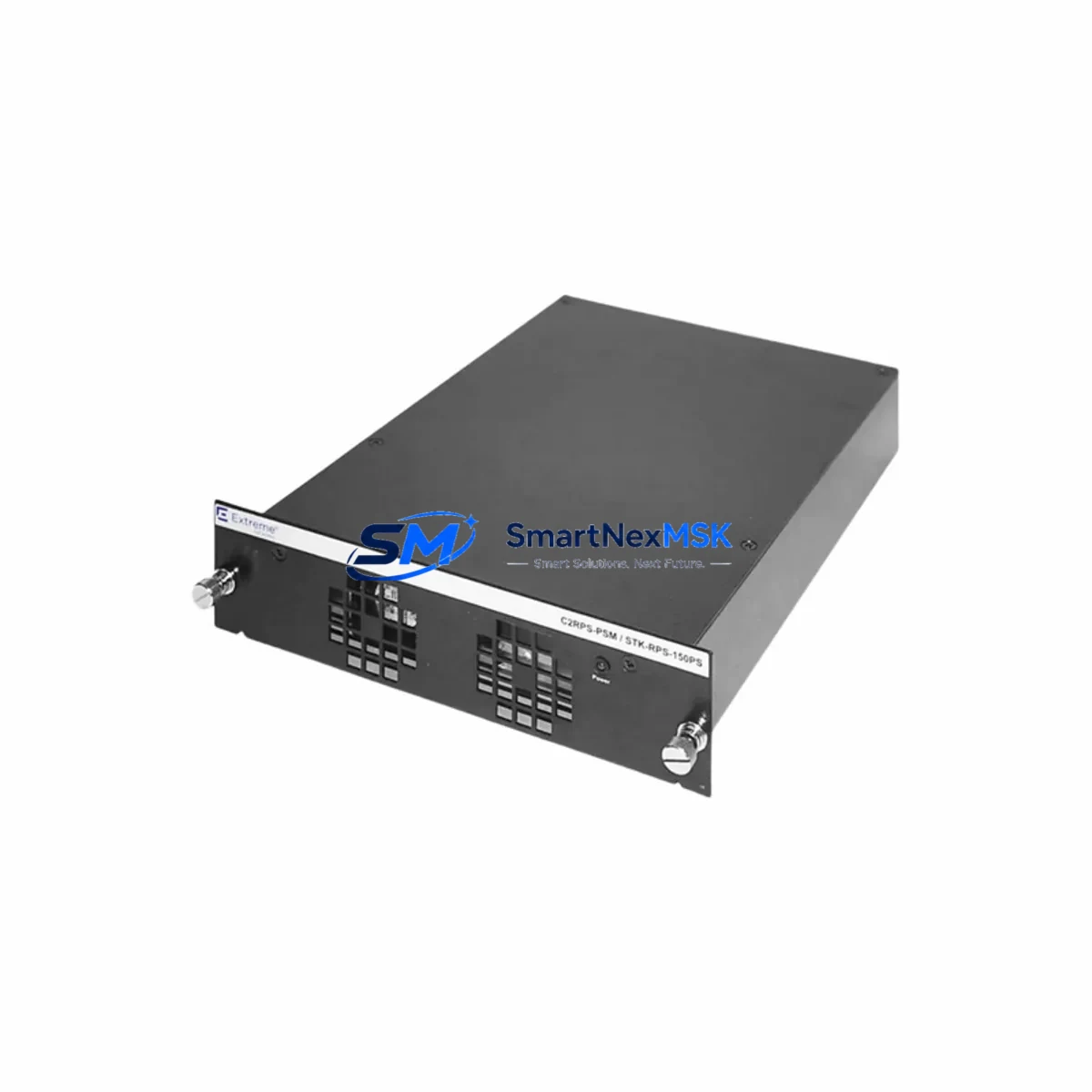
Enterasys STK-RPS-150PS Retrofit-Ready Redundant Power Supply for Stackable Series Control Systems
The Enterasys STK-RPS-150PS is a retrofit-ready redundant power supply module engineered for seamless integration into legacy Enterasys Stackable Series network and control infrastructure. As industrial facilities and enterprise environments continue to modernize aging control architectures, the STK-RPS-150PS serves as a critical drop-in replacement that eliminates single points of power failure without requiring chassis redesign, rewiring, or firmware migration. Whether you are upgrading an end-of-life power subsystem, recovering from a failed OEM unit, or proactively hardening a production control cabinet, this module delivers the reliability and compatibility your system demands.
Upgrade Compatibility Table
| Parameter | Details |
|---|---|
| Compatible Platform | Enterasys Stackable Series (STK chassis family) |
| Replaces / Supersedes | STK-RPS-150PS (OEM), equivalent third-party RPS units rated 150W |
| Installation Requirement | Tool-free hot-swap bay insertion; no chassis modification required |
| Power Output | 150W redundant; auto-failover on primary PSU fault |
| Communication Compatibility | Passive power module; no protocol configuration required |
| Connector / Interface | Proprietary STK backplane power connector; direct pin-compatible |
| Retrofit Recommendation | Recommended for all STK chassis running 24/7 critical loads |
| Commissioning Focus | Verify seating, LED status confirmation, load-sharing balance check |
| Warranty | 12-Month Warranty — covers manufacturing defects and functional failure |
Retrofit Planning for Existing Automation Systems
Integrating the STK-RPS-150PS into an existing control environment requires a structured assessment of the surrounding power distribution and chassis ecosystem. Before installation, engineers should audit the total power draw of all installed line cards and switching modules within the STK chassis. In a typical Stackable Series deployment, the chassis may host a combination of 10/100 copper I/O modules, Gigabit uplink modules, and management cards — each contributing to the aggregate load that the redundant supply must be capable of sustaining independently during a primary PSU failure event.
When planning the retrofit, technicians should also account for the STK-RPS-150PS interaction with the chassis midplane and backplane bus. Unlike modular DIN-rail power supplies used in PLC control cabinets — such as 24VDC SITOP or Phoenix Contact QUINT series units — the STK-RPS-150PS operates on an AC input architecture with internal conversion, meaning upstream UPS or PDU capacity must be verified before commissioning. If the control cabinet also houses a Siemens S7-300 or S7-400 rack with a PS 307 or PS 405 power supply module, ensure that the AC branch circuit feeding the STK chassis is on a separate breaker to prevent cross-load interference during failover testing.
For facilities running mixed-vendor environments — for example, pairing Enterasys Stackable switches with Allen-Bradley ControlLogix or CompactLogix PLCs communicating over EtherNet/IP — the STK-RPS-150PS replacement should be scheduled during a planned maintenance window. The network switch chassis provides the EtherNet/IP backbone for I/O adapter modules, remote I/O racks, and HMI communication links. A power interruption to the switch chassis, even momentary, can trigger I/O faults on 1756-EN2T or 1756-EN3TR communication modules and may require a controller re-scan or connection re-establishment from the Studio 5000 programming environment.
Similarly, if the Stackable Series chassis supports PROFINET or Modbus TCP traffic to field devices — including Siemens ET 200SP distributed I/O stations, Beckhoff EtherCAT terminals, or Schneider Electric Modicon M340 remote I/O drops — the redundant power supply ensures that network continuity is maintained even during primary PSU degradation. Technicians should document all active communication links and verify that managed switch port configurations, VLANs, and QoS settings are preserved after the module swap. Configuration backup via the Enterasys Network Management System or equivalent SNMP-based tool is strongly recommended prior to any hardware intervention.
Upon physical installation of the STK-RPS-150PS, confirm that the module is fully seated in the RPS bay, the retention latch is engaged, and the front-panel LED transitions from amber (standby) to green (active redundancy confirmed). Load-sharing balance between the primary and redundant supplies should be verified using the chassis management interface or CLI. All replacement units supplied by SMARTNEXMSK are pre-tested under load conditions prior to shipment, with test records available upon request.
Downtime Control During System Migration
Minimizing unplanned downtime is the primary concern when replacing power infrastructure in a live control environment. The STK-RPS-150PS supports hot-swap replacement in chassis that are already operating with a functional primary PSU, meaning the swap can be executed without powering down the chassis or interrupting network traffic. This is critical in facilities where the Stackable Series switch provides the sole network path for SCADA polling, DCS historian data collection, or real-time HMI updates to operator workstations.
Before initiating the swap, engineers should confirm that the primary PSU is still operational and capable of sustaining full chassis load independently during the brief period when the redundant bay is vacant. If the primary PSU is already degraded or in fault state, a controlled shutdown sequence should be planned — including notifying the DCS or PLC controller (such as a Siemens S7-1500 or Rockwell Automation ControlLogix L8x series) to enter a safe hold state, suspending non-critical I/O polling, and saving the current HMI screen state on the SCADA server.
After the new STK-RPS-150PS is installed and confirmed active, restore all communication links in reverse order: first verify Layer 2 connectivity, then confirm EtherNet/IP or PROFINET device connections, and finally validate that all remote I/O modules and HMI panels have re-established their sessions. Log the event in the site maintenance record and update the spare parts inventory to reflect the consumed unit. SMARTNEXMSK maintains in-stock availability of the STK-RPS-150PS to support rapid dispatch for emergency replacement scenarios, with same-day shipping available for orders confirmed before 14:00 CST.
Retrofit Support FAQ
Q1: Is the STK-RPS-150PS a direct drop-in replacement for the original Enterasys OEM unit?
Yes. The STK-RPS-150PS supplied by SMARTNEXMSK is dimensionally and electrically equivalent to the original Enterasys OEM redundant power supply. It uses the same proprietary backplane connector and is compatible with all STK chassis variants that support the RPS bay. No firmware update or chassis reconfiguration is required.
Q2: What pre-installation checks are required before swapping the module?
Verify that the primary PSU is functional and carrying full chassis load. Confirm AC input voltage at the chassis inlet matches the module’s rated input range. Inspect the RPS bay for debris or bent connector pins. Back up the chassis configuration via CLI or SNMP before proceeding. If the chassis is in a critical network path, notify all upstream SCADA or DCS operators before initiating the swap.
Q3: Does the replacement unit come with a warranty, and what does it cover?
All STK-RPS-150PS units supplied by SMARTNEXMSK include a 12-month warranty covering manufacturing defects and functional failure under normal operating conditions. The warranty does not cover damage resulting from incorrect installation, overvoltage events, or physical mishandling. Warranty claims are processed within 5 business days of receipt of the returned unit.
Q4: Can this module be used in a chassis that also runs PROFINET or EtherNet/IP traffic to PLC I/O systems?
Yes. The STK-RPS-150PS is a passive power module and has no interaction with the data plane or protocol stack of the switch chassis. It is fully compatible with chassis configurations running EtherNet/IP, PROFINET, Modbus TCP, or any other Layer 2/3 protocol. Replacing the RPS module will not affect VLAN configurations, port settings, or active protocol sessions, provided the swap is performed while the primary PSU remains operational.
© 2026 SMARTNEXMSK. All rights reserved.
Original Source: https://smartnexmsk.com
Contact: sales@smartnexmsk.com | +86 18259474341