FACTS F4-16AD-2 Retrofit-Ready Analog Input for F4 Series Control Systems
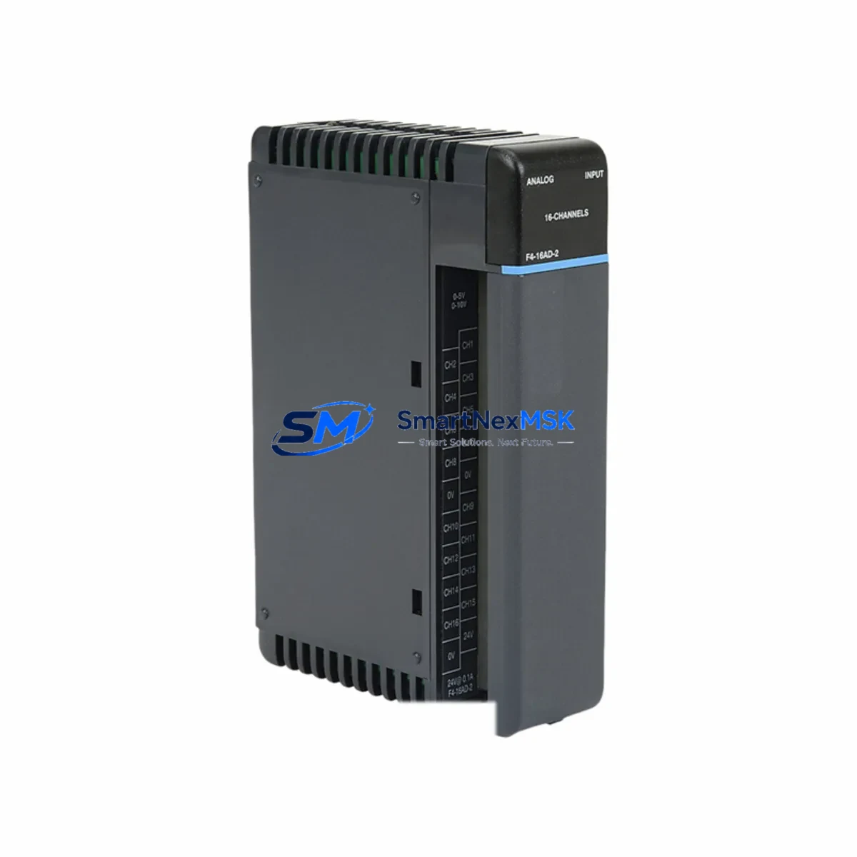
The FACTS Engineering F4-16AD-2 is a 16-channel dual-range analog input module purpose-built for the F4 Series programmable logic controller platform. As legacy F4 Series control systems approach end-of-life and original spare parts become increasingly scarce, the F4-16AD-2 serves as a verified drop-in replacement and a reliable upgrade path for facilities managing aging automation infrastructure. Whether you are restoring a failed analog input card, modernizing a multi-rack control cabinet, or migrating signal acquisition from an obsolete DL405-era architecture, this module delivers the electrical compatibility, channel density, and firmware transparency required for a smooth, low-risk retrofit.
The F4-16AD-2 accepts both 4–20 mA current loop and 0–10 VDC voltage signals across all 16 channels, making it directly interchangeable with earlier single-range analog input modules in the same rack. Field wiring terminations follow the standard F4 Series screw-terminal layout, which means existing cable harnesses and marshalling panels can be reused without modification. The module occupies a single slot on the F4 Series backplane and is addressed through the standard I/O configuration table in the host CPU — no additional configuration hardware or proprietary software license is required beyond the existing DirectSOFT or compatible programming environment already in use on site.
Upgrade Compatibility Table
| Parameter | F4-16AD-2 (This Module) | Notes / Retrofit Guidance |
|---|---|---|
| Input Channels | 16 (dual-range) | Replaces 8-ch or single-range predecessors; verify I/O map offsets |
| Signal Range | 4–20 mA / 0–10 VDC | Confirm field transmitter output type before installation |
| Backplane Interface | F4 Series standard slot | Compatible with F4-04B, F4-08B, and F4-16B backplane assemblies |
| Terminal Wiring | Screw-terminal, standard pitch | Existing harnesses reusable; inspect insulation before reuse |
| Module Addressing | Rack/slot auto-detect | Update I/O configuration table in CPU after slot change |
| Communication | Local backplane bus | No additional network adapter required for local rack installation |
| Power Consumption | Verify against F4 Series PSU rating | Check F4-PS24 or equivalent power supply headroom before adding module |
| Programming Software | DirectSOFT compatible | Existing ladder logic programs require no rewrite for direct replacement |
| Warranty | 12 Months | Covers manufacturing defects; includes pre-shipment functional test |
| Replacement Path | Direct drop-in for F4-16AD-1 | Dual-range upgrade from single-range predecessor |
Retrofit Planning for Existing Automation Systems
Successful integration of the F4-16AD-2 into an existing control system begins well before the module arrives on site. The first step is a power budget audit of the host rack. The F4 Series power supply — typically an F4-PS24 24 VDC unit or an F4-PS120 AC-input variant — must have sufficient remaining capacity to support the additional analog input circuitry. If the rack is already near its rated load due to coexisting modules such as an F4-08DA-2 analog output module, an F4-16NE3 high-density discrete input card, or an F4-08TR relay output module, a power supply upgrade or load redistribution across a second rack may be necessary before the analog input module is installed.
Next, review the backplane slot assignment. The F4 Series CPU — whether an F4-CP128 or an F4-CP256 — reads the I/O configuration table sequentially from left to right across the backplane. Inserting the F4-16AD-2 into a slot previously occupied by a different module type will shift the address map for all downstream modules unless the configuration table is updated in DirectSOFT prior to the first power-on. Failure to update the table is one of the most common causes of nuisance faults during analog input retrofits and can trigger false over-range alarms on connected process transmitters.
Field wiring verification is equally critical. Each of the 16 input channels should be loop-checked against the original P&ID drawings to confirm signal source, transmitter supply voltage, and shielding continuity. In installations where the F4-16AD-2 is replacing a failed card rather than a planned upgrade, it is common to find that one or more transmitters — such as pressure transducers, flow meters, or temperature transmitters wired to the original module — have also degraded and should be replaced concurrently to avoid repeat callouts.
For systems that include an F4-MAS remote I/O master or an H4-ECOM Ethernet communication module for supervisory data acquisition, verify that the analog channel data registers referenced in the SCADA or HMI tag database — including any Productivity Suite or DirectSOFT-linked HMI screens — are updated to reflect the new channel count and register offsets introduced by the dual-range F4-16AD-2. This is particularly important in facilities where the original HMI graphics were built against a single-range 8-channel predecessor and the operator display scaling factors are embedded in the screen objects rather than in the PLC program.
Downtime Control During System Migration
Minimizing production downtime during an analog input module swap requires a structured hot-swap protocol even though the F4 Series backplane does not support live module insertion. The recommended approach is to pre-configure and bench-test the replacement F4-16AD-2 against a spare F4 Series rack before the scheduled maintenance window. Load the existing CPU program into a laptop running DirectSOFT, verify that the I/O configuration table matches the target rack layout, and confirm that all 16 analog input channels resolve to the correct data registers in the program’s V-memory map.
During the maintenance window, power down the rack in the correct sequence — field devices first, then the F4 Series power supply — to prevent voltage transients from damaging the new module’s input circuitry. After seating the F4-16AD-2 and restoring power, perform a channel-by-channel loop check using a calibrated 4–20 mA signal source before releasing the system to automatic control. Document the as-found and as-left readings for each channel to satisfy quality records and to establish a baseline for future predictive maintenance. The entire swap, including loop checks on all 16 channels, can typically be completed within a two-hour planned outage window when pre-commissioning work has been completed in advance.
Original ladder logic programs developed for the predecessor module require no structural rewrite for a direct replacement scenario. However, if the retrofit is part of a broader migration from an F4 Series platform to a newer Productivity2000 or Productivity3000 controller architecture, the analog input scaling blocks and PID loop parameters will need to be re-mapped to the new instruction set. In that case, retaining the F4-16AD-2 as an interim solution while the new controller is commissioned in parallel is a proven strategy for maintaining continuous process control without a hard cutover.
Retrofit Support FAQ
Q: Is the F4-16AD-2 a direct replacement for the F4-16AD-1?
A: Yes. The F4-16AD-2 is the dual-range successor to the single-range F4-16AD-1 and occupies the same backplane slot with identical terminal wiring. The primary difference is the addition of a selectable 4–20 mA input range alongside the original 0–10 VDC range. No wiring changes are required for existing voltage-input channels; current-loop channels require only the selection of the appropriate range jumper or software configuration bit as documented in the F4-16AD-2 user manual.
Q: What commissioning steps are required after installation?
A: After seating the module and restoring rack power, open the I/O configuration table in DirectSOFT and confirm that the F4-16AD-2 is recognized in the correct slot. Perform a full 16-channel loop check using a calibrated signal source. Verify that analog values resolve correctly in the CPU’s V-memory registers and that any HMI scaling or alarm setpoints reflect the dual-range capability of the new module. Record as-left calibration readings for each channel.
Q: Can the F4-16AD-2 be used in a rack that also contains communication modules?
A: Yes. The F4-16AD-2 coexists with F4 Series communication modules including the H4-ECOM Ethernet adapter and F4-MAS remote I/O master without conflict, provided the rack power budget is sufficient. Ensure that the total current draw of all installed modules — including discrete I/O, analog, and communication cards — does not exceed the rated output of the installed F4 Series power supply.
Q: What does the 12-month warranty cover?
A: Every F4-16AD-2 unit shipped by SMARTNEXMSK undergoes a pre-shipment functional test covering all 16 analog input channels across both signal ranges. The 12-month warranty covers manufacturing defects and functional failures under normal operating conditions. Warranty claims are supported by our technical team at sales@smartnexmsk.com. Replacement or repair is initiated within one business day of a confirmed defect report.
© 2026 SMARTNEXMSK. All rights reserved.
Original Source: https://smartnexmsk.com
Contact: sales@smartnexmsk.com | +86 18259474341