FAST FIO01-1 P-900163 Retrofit-Ready I/O Module for FAST Control Systems
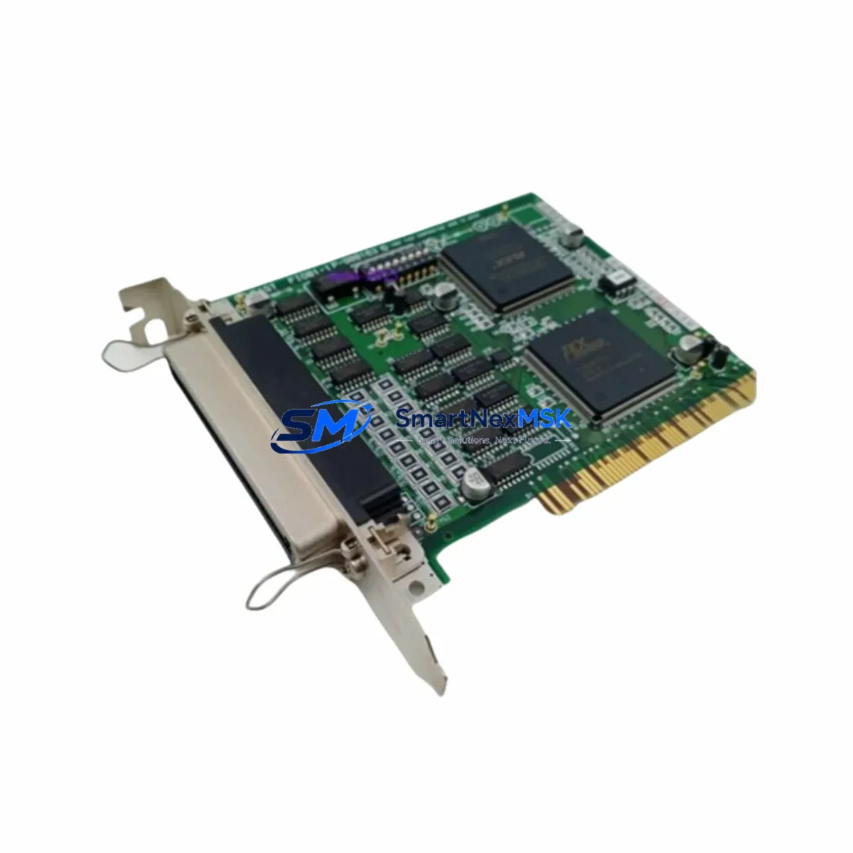
The FAST FIO01-1 (P-900163) is a field-proven I/O module engineered for seamless integration into FAST automation platforms. As legacy control architectures reach end-of-life, this module serves as a direct retrofit solution for facilities operating aging FAST I/O Series racks, enabling engineers to restore full I/O capacity without redesigning the control cabinet or rewriting core PLC logic. Whether you are replacing a failed unit, expanding an existing I/O rack, or executing a phased system modernization, the FIO01-1 P-900163 delivers the compatibility, reliability, and supply continuity that industrial operations demand.
SMARTNEXMSK maintains verified stock of the FIO01-1 P-900163 with full pre-shipment functional testing, ensuring every unit leaves our facility ready for immediate field installation. Each module is covered by a 12-month warranty and ships with traceable documentation to support your maintenance records and audit requirements.
Upgrade Compatibility Table
| Parameter | Details |
|---|---|
| SKU / Part Number | FIO01-1 / P-900163 |
| Brand / Manufacturer | FAST (Zhejiang SUPCON / FAST Automation) |
| Module Series | FAST FIO I/O Series |
| Module Type | Field I/O Module |
| Backplane / Rack Interface | Compatible with FAST I/O Series backplane and rack assemblies |
| Communication Protocol | FAST proprietary I/O bus; compatible with FAST controller communication links |
| Installation Requirement | DIN rail or rack-mount; verify slot addressing before installation |
| Power Supply Compatibility | Powered via backplane; confirm rack PSU capacity before adding modules |
| Replacement Scope | Direct drop-in for failed or discontinued FIO01-1 units in existing racks |
| Commissioning Notes | Verify module address, I/O channel mapping, and HMI tag binding post-installation |
| Warranty | 12 months from date of shipment |
| Origin | China (CN) |
Retrofit Planning for Existing Automation Systems
Successful retrofit of the FIO01-1 P-900163 into an operational control system requires a structured pre-installation review. Before removing the legacy module, engineers should document the existing I/O channel assignments, terminal wiring labels, and module slot address configured in the FAST controller. In systems where the FIO01-1 shares a rack with a FAST FPU power supply module, it is critical to verify that the rack’s total power budget accommodates the replacement unit without triggering under-voltage faults on adjacent modules.
In multi-rack configurations, the FIO01-1 P-900163 typically operates alongside other FAST FIO Series modules such as the FIO02-1 analog input module and the FIO03-1 analog output module, which handle 4–20 mA process signals from field transmitters and control valves. When upgrading a rack that also contains a FAST FCU controller module, confirm that the controller firmware version supports the FIO01-1 hardware revision being installed — firmware mismatches are a common source of I/O initialization errors during commissioning.
For facilities migrating from older FAST DCS architectures, the FIO01-1 P-900163 is frequently deployed in conjunction with a FAST communication gateway module to bridge legacy field bus segments (such as PROFIBUS DP or Modbus RTU) to the modernized control network. If the existing control cabinet includes a FAST FDI01 digital input module or FAST FDO01 digital output module on the same backplane, these modules should be inspected for terminal block condition and wiring integrity before the retrofit proceeds, as degraded terminal connections are a leading cause of intermittent I/O faults in aging systems.
HMI integration is another key checkpoint. After installing the FIO01-1 P-900163, operators should verify that all associated HMI screen tags — particularly those linked to process alarms, interlock status, and manual override controls — correctly reflect the new module’s I/O channel data. In systems using a FAST operator station (OS) or a third-party SCADA platform connected via OPC-DA or OPC-UA, a full tag scan and alarm acknowledgment test should be completed before returning the loop to automatic control.
Where the retrofit involves I/O expansion rather than direct replacement, engineers should also review the rack’s available slot count and confirm that the FAST FIO backplane supports the additional module without requiring a chassis upgrade. In some legacy installations, the existing backplane may be at capacity, necessitating the addition of a FAST expansion rack and a corresponding rack interconnect cable to extend the I/O bus.
Downtime Control During System Migration
Minimizing unplanned downtime is the primary operational concern when replacing an I/O module in a live production environment. The recommended approach is to perform a controlled hot-swap procedure where the process permits, or to schedule the replacement during a planned maintenance window with a pre-staged FIO01-1 P-900163 unit that has been bench-tested and address-configured in advance.
Before initiating the swap, export and archive the current controller program from the FAST FCU or equivalent controller module using the FAST engineering workstation software. This backup preserves the I/O mapping, PID tuning parameters, interlock logic, and communication configuration, ensuring that any unexpected program corruption during the replacement can be recovered within minutes rather than hours.
During the physical swap, follow a structured sequence: place the affected control loop in manual mode at the HMI, isolate the field wiring at the terminal block, remove the failed FIO01-1, seat the replacement module firmly into the backplane slot, and restore field wiring using the pre-documented terminal layout. After power-up, confirm that the controller recognizes the new module at the correct rack address before releasing the loop back to automatic. A channel-by-channel I/O verification test — comparing live field signals against HMI readings — should be completed and signed off before the maintenance window closes.
For critical processes where even a brief interruption is unacceptable, consider deploying a temporary bypass using a portable I/O simulator connected to the field wiring while the module swap is performed. This approach maintains signal continuity to the controller and prevents spurious alarms or interlock trips during the replacement interval.
Retrofit Support FAQ
Q1: Is the FAST FIO01-1 P-900163 a direct replacement for the original FIO01-1 installed in my existing rack?
Yes. The FIO01-1 P-900163 is the manufacturer part number for the standard FIO01-1 I/O module and is designed as a direct slot-compatible replacement for units of the same designation. No mechanical modification to the rack or backplane is required. Verify the hardware revision label on the original module and confirm compatibility with your controller firmware version before installation.
Q2: What wiring and terminal checks should I perform before installing the replacement module?
Inspect all field wiring terminals on the adjacent terminal block for corrosion, loose connections, and correct wire gauge. Re-torque all terminal screws to the specified value and verify that cable shielding is properly grounded at the cabinet earth bar. Cross-reference the existing wiring diagram against the channel assignment table in the FIO01-1 installation manual to confirm that each field signal is connected to the correct I/O channel before powering up the new module.
Q3: How do I verify communication link integrity after installing the FIO01-1 P-900163?
After installation, use the FAST engineering workstation to perform an online module scan. Confirm that the FIO01-1 appears in the I/O configuration tree at the correct rack and slot address. Check the module status LED indicators for normal operating state (typically solid green). Run a forced I/O test on each channel to verify that field signals are correctly read and written before releasing the system to automatic operation.
Q4: What does the 12-month warranty cover, and how is it supported?
Every FIO01-1 P-900163 shipped by SMARTNEXMSK is covered by a 12-month warranty from the date of shipment. The warranty covers manufacturing defects and functional failures under normal operating conditions. Each unit undergoes pre-shipment functional testing and ships with a test report. In the event of a warranty claim, contact our technical support team with the order reference and failure description; we will arrange priority replacement to minimize your system downtime.
© 2026 SMARTNEXMSK. All rights reserved.
Original Source: https://smartnexmsk.com
Contact: sales@smartnexmsk.com | +86 18259474341