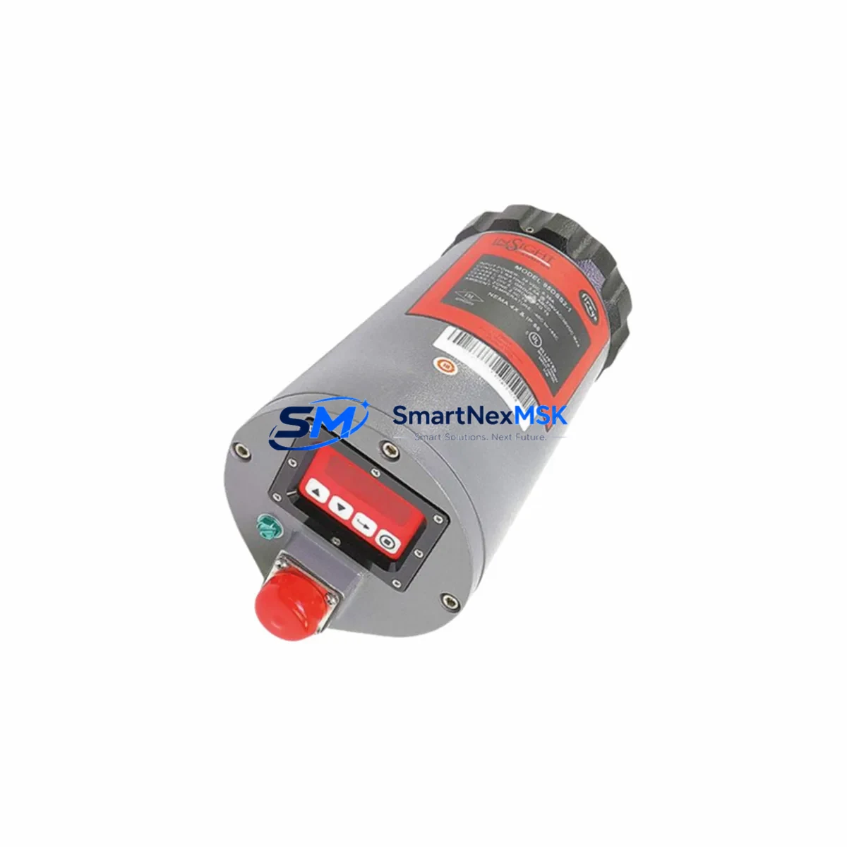
FIREYE 95DSS2E-1 Maintenance-Ready Spare 95 Series Automation
Unplanned burner shutdowns caused by a failed flame scanner can cascade into hours of lost production, emergency maintenance callouts, and costly refractory cool-down cycles. The FIREYE 95DSS2E-1 dual-spectrum infrared flame scanner is a critical front-line component in 95 Series combustion management systems, and maintaining a verified spare on the shelf is the single most effective action a maintenance engineer can take to protect continuous operation. This listing provides an original FIREYE 95DSS2E-1 unit — fully tested prior to shipment, supplied with a 12-month warranty, and ready for immediate drop-in replacement in any 95 Series burner management panel.
The 95DSS2E-1 employs dual-spectrum infrared detection to discriminate between true flame and background radiation, making it suitable for gas, oil, and combination-fuel burners across power generation, petrochemical, food processing, and heavy industrial environments. Its compact housing mounts directly to standard FIREYE 95 Series scanner ports without adapter hardware, and the signal output is fully compatible with the FIREYE 95UVS, 95UV5-1, and E110 flame amplifier modules already installed in most legacy panels. Procurement engineers sourcing a replacement can confirm compatibility by cross-referencing the existing amplifier model number and scanner port thread specification before ordering.
Spare Maintenance Table
| Parameter | Specification |
|---|---|
| Model / SKU | FIREYE 95DSS2E-1 |
| Series | FIREYE 95 Series |
| Detection Technology | Dual-Spectrum Infrared (IR) |
| Fuel Compatibility | Gas, Oil, Combination Fuel |
| Supply Voltage | Per 95 Series amplifier module (typically 120 VAC / 24 VDC) |
| Output Signal | Compatible with FIREYE 95 Series flame amplifiers |
| Mounting | Standard 95 Series scanner port, direct fit |
| Operating Temperature | Up to 125 °C ambient (scanner body); cooling air recommended above 50 °C |
| Ingress Protection | Industrial-grade enclosure, suitable for boiler room environments |
| Compatible Amplifiers | FIREYE 95UVS, 95UV5-1, E110 series |
| Application | Burner management, combustion supervision, flame safeguard |
| Origin | USA (FIREYE / UTC Fire & Security) |
| Condition | Original spare, pre-shipment tested |
| Warranty | 12 Months from date of shipment |
| Shipping | Worldwide express; ESD-safe packaging |
Maintenance Planning for Continuous Operation
A structured maintenance plan for any 95 Series burner management system should treat the 95DSS2E-1 as part of a broader inspection scope. When a maintenance team is called to investigate a nuisance flame-failure trip or a scanner signal dropout, the root cause is rarely isolated to the scanner alone. The following components in the same electrical circuit and control cabinet should be inspected concurrently to avoid repeat failures after the scanner is replaced.
Begin with the FIREYE 95UVS or E110 flame amplifier — the amplifier processes the scanner’s raw signal and is subject to relay contact wear and capacitor aging. A scanner that tests good on the bench may still produce intermittent trips if the amplifier’s sensitivity trim is drifted or its output relay is pitted. Next, inspect the scanner cable and connector assembly: the coaxial cable between the 95DSS2E-1 and the amplifier is a frequent failure point in high-vibration or high-temperature installations; look for cracked insulation, corroded BNC connectors, and loose strain-relief fittings. The burner management relay module (such as the FIREYE BurnerPRO or equivalent safety relay) should have its contact resistance verified — a high-resistance contact can mask a healthy scanner signal and trigger spurious lockouts.
On the power supply side, confirm that the 24 VDC or 120 VAC control power supply feeding the amplifier rail is within tolerance; voltage sag under load is a common cause of false flame-failure signals in aging panels. Check the terminal block connections on the amplifier input and output circuits — loose screw terminals cause intermittent continuity faults that are difficult to reproduce during static testing. If the panel includes a signal isolator or loop-powered isolator between the scanner circuit and the DCS/PLC input card, verify that the isolator’s output is within the expected 4–20 mA or discrete voltage range.
For systems integrated with a Siemens S7 or Allen-Bradley ControlLogix PLC, confirm that the digital input card assigned to the flame-proven signal is reading correctly and that the input filter time is set appropriately for the scanner’s response speed. Where an HMI panel (such as a Siemens TP700 or Allen-Bradley PanelView) displays burner status, verify that the flame-proven tag is mapped correctly after any scanner replacement. Finally, inspect the fuse and circuit protection on the scanner supply circuit — a slow-blow fuse rated for the amplifier’s inrush current should be in place, and any fuse that shows discoloration should be replaced as a precaution even if it has not yet opened.
Site Replacement Workflow
Replacing the FIREYE 95DSS2E-1 on a live industrial site follows a straightforward sequence that minimizes downtime and ensures system compatibility is maintained throughout the process.
Step 1 — Isolate and lock out: Follow site LOTO procedures for the burner circuit. Confirm that the burner management system is in a safe, locked-out state before approaching the scanner port.
Step 2 — Document the existing installation: Photograph the scanner orientation, cable routing, and connector labeling before removal. Note the amplifier sensitivity setting (if adjustable) so it can be restored after replacement.
Step 3 — Remove the failed unit: Disconnect the coaxial cable at the scanner end. Unscrew the 95DSS2E-1 from the scanner port. Inspect the port threads and gasket seat for damage or carbon buildup; clean as required.
Step 4 — Install the replacement unit: Thread the new 95DSS2E-1 into the scanner port by hand first, then torque to the manufacturer’s specification. Reconnect the coaxial cable and verify the connector is fully seated and locked.
Step 5 — Restore power and verify signal: Re-energize the amplifier circuit. With the burner in a controlled test-fire condition, confirm that the amplifier’s flame-proven LED illuminates and that the output relay closes within the expected response time. Check the HMI or DCS for a clean flame-proven signal with no spurious dropouts over a minimum 5-minute observation period.
Step 6 — Update maintenance records: Log the replacement date, new unit serial number, and post-installation test results. Schedule the next scanner inspection interval per the OEM’s recommended maintenance cycle (typically 12 months or 8,000 operating hours, whichever comes first).
This workflow applies equally to planned maintenance replacements and emergency callouts, and it is compatible with both legacy 95 Series panels and modernized burner management systems that retain the original FIREYE scanner interface.
Spare Parts Support FAQ
Q1: Is the 95DSS2E-1 a direct drop-in replacement for older FIREYE 95 Series scanners?
Yes. The 95DSS2E-1 is designed as a direct mechanical and electrical replacement for earlier dual-spectrum scanner variants used in the FIREYE 95 Series platform. No adapter hardware or amplifier reconfiguration is required for standard installations. If your existing amplifier is an E110 or 95UVS model, compatibility is confirmed. For non-standard or modified panels, please provide the amplifier model number and we will verify compatibility before shipment.
Q2: What pre-shipment testing is performed on each unit?
Every 95DSS2E-1 unit is functionally tested prior to dispatch. Testing includes signal output verification under simulated flame conditions, connector integrity check, and visual inspection of the optical window and housing. A test report is available upon request. Units are shipped in ESD-safe, anti-vibration packaging to preserve condition during transit.
Q3: What does the 12-month warranty cover, and how is a warranty claim handled?
The 12-month warranty covers manufacturing defects and functional failures under normal operating conditions from the date of shipment. It does not cover damage caused by incorrect installation, overvoltage, physical impact, or operation outside the specified environmental limits. To initiate a warranty claim, contact sales@smartnexmsk.com with the order number, installation date, and a description of the fault. Replacement units are dispatched after fault confirmation, and failed units are returned for analysis at our cost.
Q4: Can you support long-term or blanket-order supply for maintenance programs?
Yes. We support scheduled spare parts programs for maintenance teams that require guaranteed stock availability across multiple planned outage windows. Blanket orders for the 95DSS2E-1 and associated 95 Series components — including amplifier modules, scanner cables, and relay assemblies — can be arranged with agreed lead times and fixed pricing. Contact our sales team to discuss volume requirements and delivery scheduling.
© 2026 SMARTNEXMSK. All rights reserved.
Original Source: https://smartnexmsk.com
Contact: sales@smartnexmsk.com | +86 18259474341