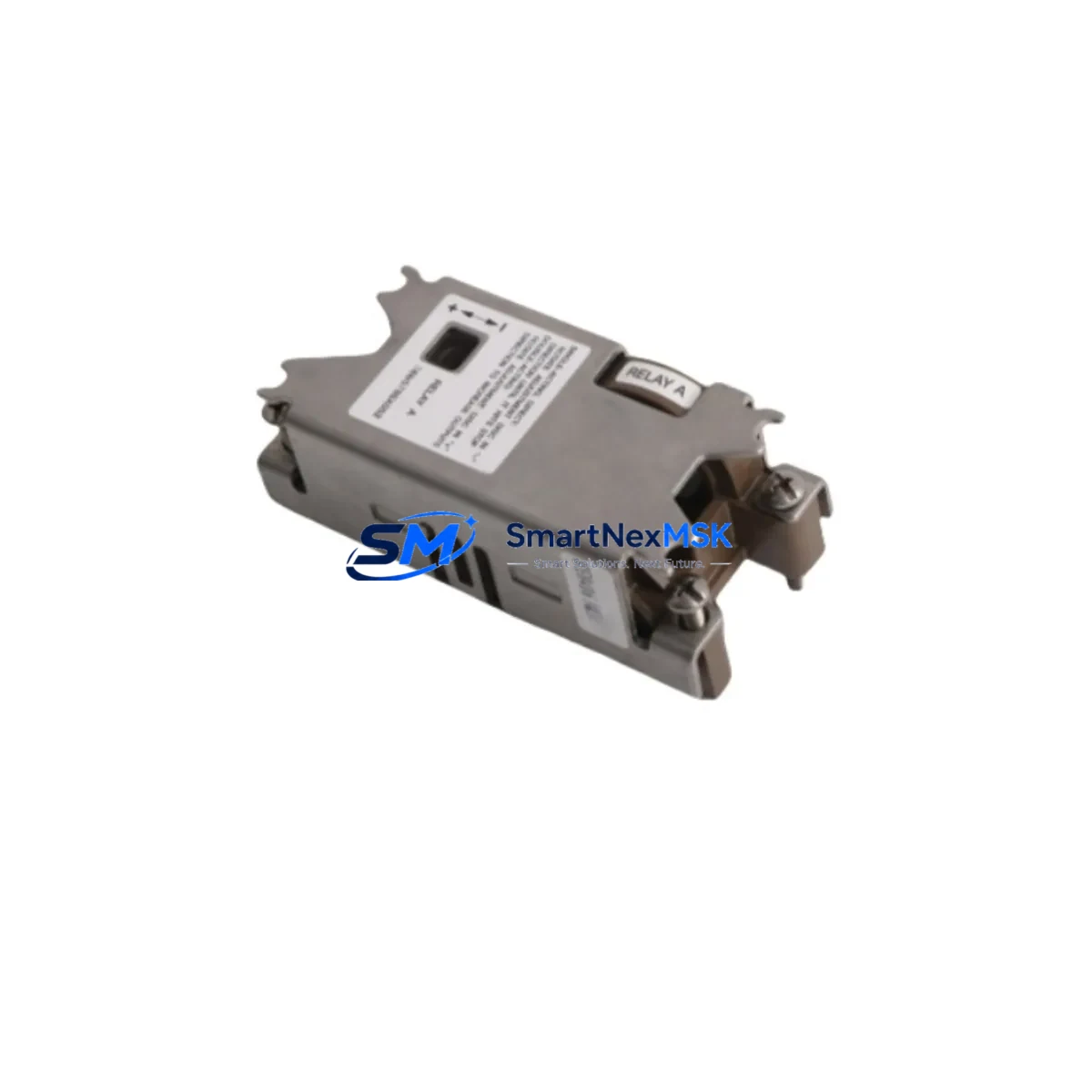
Fisher 38B5786X112 Retrofit-Ready Pneumatic Relay for DVC6000 Control Systems
The Fisher 38B5786X112 is a precision-engineered pneumatic relay module designed as a retrofit-ready replacement for Emerson Fisher DVC6000 series digital valve controllers. Whether you are managing a planned upgrade of aging positioner assemblies, recovering from an unplanned failure on a critical control loop, or modernizing a legacy pneumatic control cabinet, the 38B5786X112 delivers verified drop-in compatibility with minimal engineering intervention. Each unit is sourced, inspected, and dispatched with a 12-month warranty, backed by in-stock inventory for rapid global fulfillment.
The DVC6000 platform remains one of the most widely deployed digital valve controller families in process industries including oil and gas, chemical, power generation, and pulp and paper. As original equipment ages and OEM support windows narrow, procurement teams and instrument engineers increasingly rely on verified aftermarket and surplus-stock relay modules to sustain uptime without committing to full positioner replacement. The 38B5786X112 addresses this need directly — it is a single-acting relay assembly that integrates into the DVC6000 housing without modification to the actuator stem, travel sensor, or I/P converter wiring.
Upgrade Compatibility Table
| Parameter | Details |
|---|---|
| Compatible Positioner Series | Fisher DVC6000, DVC6000f, DVC6000 SIS |
| Actuator Type | Single-Acting (Spring-Return) |
| Relay Function | Pneumatic amplification of I/P output signal |
| Supply Pressure Range | 1.4 – 10.0 bar (20 – 145 psi) |
| Installation Interface | Direct-mount to DVC6000 relay housing; no adapter required |
| Communication Compatibility | HART (4–20 mA), compatible with AMS Device Manager and ValveLink |
| Replacement Recommendation | Direct replacement for worn, leaking, or failed DVC6000 relay assemblies |
| Commissioning Notes | Auto-calibration via ValveLink SNAP-ON or AMS after installation; verify travel sensor zero and span |
| Warranty | 12 Months from date of shipment |
| Shipping | In-stock; global dispatch within 2 business days |
Retrofit Planning for Existing Automation Systems
Successful retrofit of the 38B5786X112 into an operating plant environment requires systematic pre-installation planning. Before removing the existing relay assembly, engineers should document the current DVC6000 configuration using ValveLink software — capturing travel calibration data, PID tuning parameters, alert setpoints, and any custom characterization curves stored in the positioner’s non-volatile memory. This configuration backup ensures that commissioning after relay replacement is a restoration exercise rather than a full re-calibration from scratch.
On the pneumatic supply side, confirm that the instrument air header feeding the DVC6000 is clean, dry, and regulated to within the relay’s rated supply pressure range. Contaminated or wet instrument air is a leading cause of premature relay wear and is frequently the root cause of the original failure. If the control valve is part of a safety instrumented function, coordinate with the SIS engineer to confirm that the partial stroke test schedule and proof test interval are updated to reflect the relay replacement date.
For installations where the DVC6000 is mounted on a Fisher GX Control Valve or a rotary actuator using a Fisher 1052 spring-diaphragm actuator, verify that the relay output port orientation matches the actuator’s pneumatic connection. In multi-valve skids where several DVC6000f units share a common HART multiplexer — such as a Pepperl+Fuchs or Mactek HART modem connected to a DeltaV SIS controller — confirm that the device tag and HART address are preserved during the swap to avoid address conflicts on the segment.
Instrument technicians should also inspect the DVC6000 feedback assembly, including the travel sensor magnet and the printed wiring board assembly (PWBA), for signs of corrosion or moisture ingress before reinstalling the new relay. If the positioner has been in service for more than eight years, it is prudent to simultaneously replace the I/P converter module and the relay module together to avoid a repeat outage within a short interval. The Fisher DVC6010 and DVC6020 sub-assemblies are commonly replaced alongside the relay during planned turnaround windows.
Where the control system architecture involves a Emerson DeltaV distributed control system communicating over FOUNDATION Fieldbus or HART, the relay replacement does not affect the digital communication layer — the 38B5786X112 is a purely pneumatic component downstream of the I/P transducer. However, after installation, re-run the DeltaV Valve Diagnostics module to generate a new baseline signature for the valve assembly, which will serve as the reference for future predictive maintenance alerts.
Downtime Control During System Migration
Minimizing process disruption during relay replacement on a live control loop requires a structured isolation and handover procedure. Where process conditions permit, switch the affected control loop to manual mode at the DCS — whether a Honeywell Experion PKS, Yokogawa CENTUM VP, or Emerson DeltaV — and hold the control valve at a safe fixed position before beginning mechanical work. For critical loops where manual hold is not acceptable, coordinate a brief process bypass or install a temporary pneumatic lock-up valve to maintain actuator position during the relay swap.
The physical relay replacement on a DVC6000 is a tool-accessible procedure that typically takes 20 to 40 minutes for a trained instrument technician. The relay module is secured by two captive screws and connects to the positioner body via a machined pneumatic interface — no pipe thread sealant or special tooling is required. After installation, perform a bench leak test using a regulated air supply before returning the valve to service. Reconnect the HART communicator — a Fisher 475 Field Communicator or equivalent — to verify that the positioner recognizes the new relay and that no diagnostic alerts are active.
Once the loop is returned to automatic control, monitor the valve’s travel deviation and supply pressure consumption for the first 30 minutes of operation. A correctly installed 38B5786X112 will restore the positioner’s step response and eliminate the supply pressure bleed that typically accompanies a worn or cracked relay diaphragm. Document the replacement in the plant’s CMMS system, update the positioner’s maintenance record in AMS Device Manager, and reset the partial stroke test baseline if applicable.
Retrofit Support FAQ
Q1: Is the 38B5786X112 a direct drop-in replacement for the original Fisher DVC6000 relay, or are adapter brackets required?
The 38B5786X112 is a direct drop-in replacement. It uses the same two-screw mounting interface and pneumatic port geometry as the original DVC6000 relay assembly. No adapter brackets, port reducers, or housing modifications are required. Installation follows the standard Fisher DVC6000 maintenance procedure.
Q2: How do I verify wiring and terminal compatibility before installation?
The 38B5786X112 is a pneumatic relay module with no electrical terminals — it does not interface with the 4–20 mA loop wiring or the HART communication circuit. Electrical connections to the DVC6000 PWBA and I/P converter remain undisturbed during relay replacement. Verify only the pneumatic supply and output port connections against the DVC6000 installation drawing for your specific actuator configuration.
Q3: What commissioning steps are required after installing the 38B5786X112?
After mechanical installation and leak verification, connect a HART communicator or ValveLink SNAP-ON software and run the Auto Setup routine to re-calibrate travel zero and span. If a configuration backup was taken prior to removal, restore the saved parameters. Confirm that the positioner’s diagnostic baseline — including supply pressure, travel deviation, and drive signal — is within normal operating range before returning the loop to automatic control.
Q4: What does the 12-month warranty cover, and what pre-shipment testing is performed?
Every 38B5786X112 unit is functionally tested for pneumatic integrity — including diaphragm leak-down, relay actuation response, and port flow — prior to dispatch. The 12-month warranty covers manufacturing defects and functional failure under normal operating conditions from the date of shipment. Units damaged by contaminated instrument air, over-pressure events, or improper installation are excluded. Contact our technical team for warranty claims or pre-shipment test certificates.
© 2026 SMARTNEXMSK. All rights reserved.
Original Source: https://smartnexmsk.com
Contact: sales@smartnexmsk.com | +86 18259474341