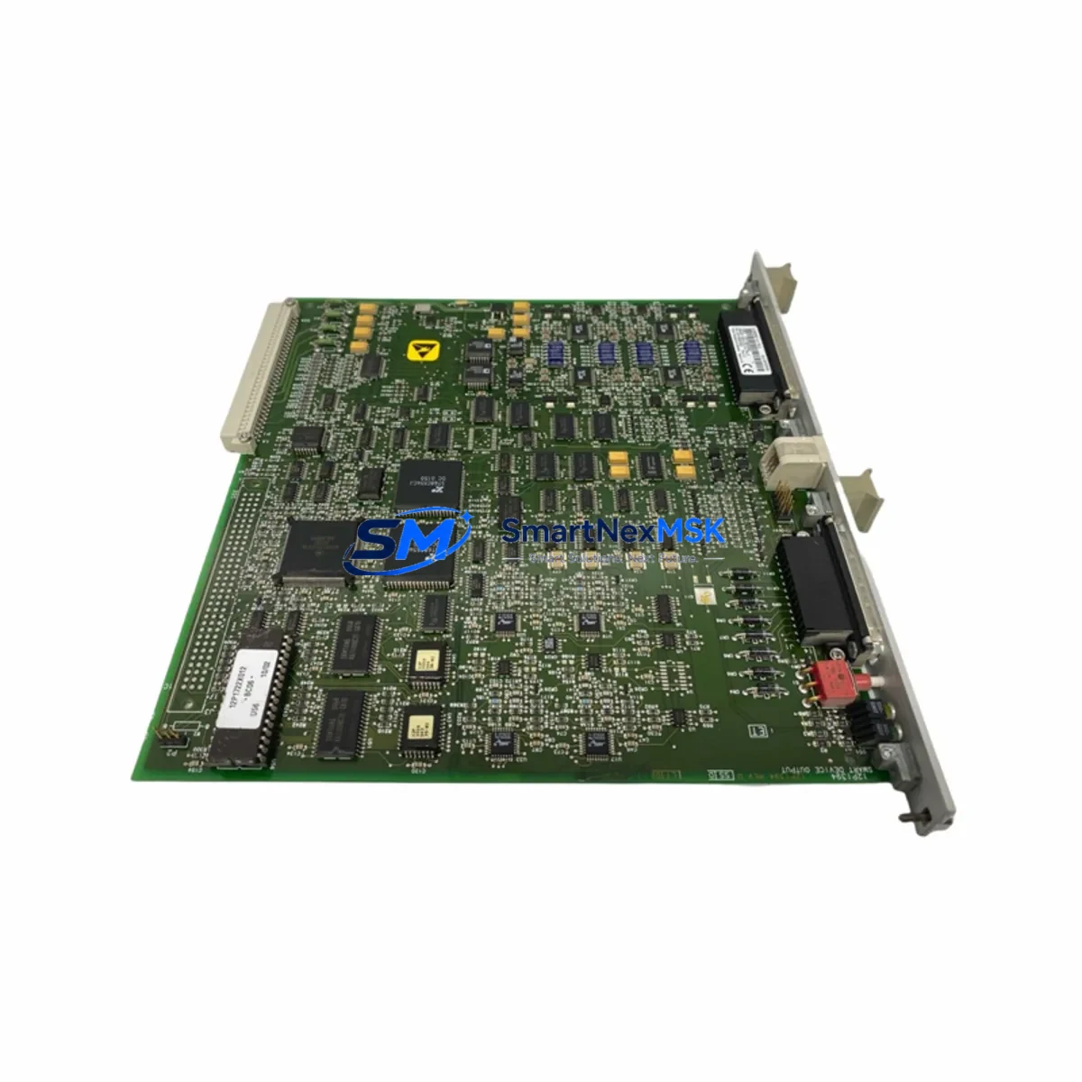
Fisher CL6828X1-A1 12P1395X062: Retrofit-Ready Output Module for DeltaV Control Systems
The Fisher CL6828X1-A1 12P1395X062 is a DeltaV-series smart output module engineered for seamless integration into legacy and active Emerson DeltaV distributed control system architectures. As industrial facilities face increasing pressure to modernize aging control infrastructure without full system overhauls, this module serves as a proven retrofit solution — enabling engineers to replace discontinued output cards, restore I/O capacity, and extend the operational life of existing DeltaV cabinets with minimal disruption to running processes.
Whether you are replacing a failed card in a critical loop, upgrading a legacy DeltaV MD or MX controller node, or expanding I/O capacity within an existing carrier assembly, the CL6828X1-A1 12P1395X062 delivers the electrical and protocol compatibility required for a controlled, low-risk migration. Its design aligns with Emerson’s DeltaV Series 2 hardware standards, supporting FOUNDATION Fieldbus H1 segment communication and direct backplane integration with standard DeltaV 8-slot and 12-slot carriers.
Upgrade Compatibility Table
| Parameter | Specification / Compatibility |
|---|---|
| Module Part Number | CL6828X1-A1 / 12P1395X062 |
| Compatible Platform | Emerson DeltaV Series 2 (MD, MX, S-Series Controllers) |
| Backplane Interface | DeltaV standard carrier backplane (8-slot / 12-slot) |
| Communication Protocol | FOUNDATION Fieldbus H1; DeltaV internal bus |
| Installation Requirement | Hot-swap capable; no carrier modification required |
| Replacement Compatibility | Direct replacement for discontinued DeltaV output cards of equivalent I/O class |
| Wiring Termination | Compatible with existing DeltaV terminal block assemblies (no rewiring required in most configurations) |
| Firmware / Software | Recognized by DeltaV Operate and DeltaV Diagnostics without additional licensing in standard configurations |
| Commissioning | Module address auto-assigned via carrier slot; verify in DeltaV Explorer post-installation |
| Warranty | 12-Month Warranty — covers manufacturing defects and functional failure under normal operating conditions |
Retrofit Planning for Existing Automation Systems
A successful retrofit using the CL6828X1-A1 12P1395X062 begins with a thorough audit of the existing DeltaV node configuration. Engineers should first confirm the power budget of the DeltaV Power Supply — typically a DeltaV PS2 or PS4 unit — to ensure the carrier has sufficient headroom to support the replacement module alongside existing cards. Overloaded power rails are a common cause of intermittent faults during post-replacement commissioning and must be ruled out before the new module is seated.
Terminal block wiring should be verified against the original loop drawings. In most DeltaV installations, the DeltaV Terminal Block Assembly (TBA) remains in place during a card swap, preserving field wiring continuity. However, if the original installation used a non-standard marshalling arrangement or a third-party junction box, technicians must confirm that signal polarity, shielding, and ground references are maintained. For FOUNDATION Fieldbus segments, the H1 segment terminator — often a DeltaV Fieldbus Power Conditioner (FPS) — must remain active and correctly terminated throughout the swap to prevent segment collapse.
Module address assignment in DeltaV is slot-based and automatic. After physical installation, the replacement module will appear in DeltaV Explorer under the corresponding controller node. Engineers should confirm that the module type recognized by the system matches the expected I/O class before downloading the control strategy. If the original module was part of a redundant I/O pair using a DeltaV CIOC (Controller I/O Card) or a redundant carrier, the secondary module must also be verified for firmware version alignment to prevent synchronization errors.
For facilities migrating from older DeltaV hardware — such as legacy DeltaV MD Plus controllers or first-generation Series 1 carriers — the CL6828X1-A1 12P1395X062 may require a carrier upgrade to a Series 2 compatible chassis. In these cases, the DeltaV 8-Slot Carrier (VE4001S2T2B2) or 12-Slot Carrier (VE4002S2T2B2) provides the correct backplane interface. The DeltaV SD Plus Controller or MD Controller should be confirmed as the node host before the I/O download is executed.
HMI integration should be validated in DeltaV Operate after the module replacement. Faceplate displays tied to the affected output channels must be checked for correct tag binding, alarm limits, and engineering unit scaling. In facilities running parallel SCADA systems via OPC-DA or OPC-UA, the data server connection should be monitored during the first 30 minutes of post-replacement operation to confirm that tag values are updating correctly and that no communication timeouts are logged.
For sites using AMS Device Manager alongside DeltaV, HART-enabled field devices connected through the output module should be re-scanned post-installation to confirm device recognition and diagnostic data continuity. Programming cables such as the DeltaV USB Engineering Cable may be required for on-site firmware verification if the module is being commissioned in a standalone test environment prior to live installation.
Downtime Control During System Migration
Minimizing process downtime during a DeltaV output module replacement requires a structured pre-outage preparation protocol. Before the maintenance window opens, engineers should export the current DeltaV control strategy and create a full system backup using DeltaV Operate’s Configuration Export function. This preserves all module assignments, tag configurations, alarm setpoints, and interlock logic, ensuring that the original program state can be restored within minutes if the replacement encounters an unexpected issue.
Where process conditions permit, affected output loops should be placed in manual mode prior to the card swap. Field operators should be briefed on the expected duration of the maintenance window and prepared to monitor critical process variables at the local panel or via a secondary control station. For loops controlling safety-critical actuators — such as emergency shutdown valves or high-integrity pressure protection systems — a formal Management of Change (MOC) review should be completed before the replacement is authorized.
The physical swap of the CL6828X1-A1 12P1395X062 is designed to be completed in under 15 minutes in a standard hot-swap scenario. After seating the module, engineers should allow 60–90 seconds for the DeltaV system to recognize and initialize the new card before attempting a control strategy download. Post-installation, a structured loop check — verifying output signal continuity from the DeltaV controller through to the field actuator — should be completed before returning affected loops to automatic control. Maintaining a detailed commissioning log throughout the process supports both internal audit requirements and future maintenance planning.
Retrofit Support FAQ
Q1: Is the CL6828X1-A1 12P1395X062 a direct drop-in replacement for discontinued DeltaV output modules?
In most DeltaV Series 2 installations, yes. The module is designed to seat into standard DeltaV carriers without mechanical modification. However, engineers should confirm the I/O class (analog output, digital output, or FOUNDATION Fieldbus) matches the original module specification before installation. If the original module was a Series 1 card, a carrier upgrade may be required.
Q2: What wiring changes are required during installation?
In standard configurations using DeltaV Terminal Block Assemblies, no field wiring changes are required. The TBA remains connected to the carrier during the card swap. For non-standard marshalling or third-party junction box arrangements, technicians should verify signal polarity and shielding continuity against the original loop drawings before powering the new module.
Q3: How is the module commissioned after installation, and what tools are needed?
After physical installation, the module is automatically recognized by the DeltaV controller via its carrier slot address. Commissioning is completed in DeltaV Explorer by confirming module type recognition, followed by a control strategy download and loop check. A DeltaV Engineering Workstation with the appropriate DeltaV software version is required. No additional licensing is needed in standard configurations.
Q4: What does the 12-month warranty cover, and how is it claimed?
The 12-month warranty covers manufacturing defects and functional failure under normal operating conditions from the date of shipment. Each unit undergoes pre-shipment functional testing to verify output signal accuracy, backplane communication, and power consumption within specification. To initiate a warranty claim, contact our technical support team with the order reference, installation date, and a description of the observed fault. Replacement or repair will be coordinated within 5 business days of claim confirmation.
© 2026 SMARTNEXMSK. All rights reserved.
Original Source: https://smartnexmsk.com
Contact: sales@smartnexmsk.com | +86 18259474341