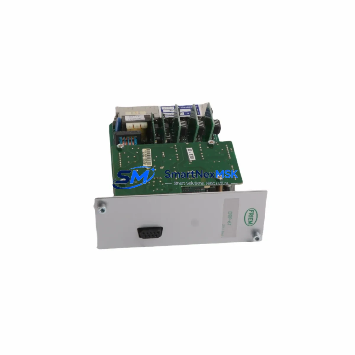
FRIEM DRP-6T Maintenance-Ready Spare for DRP Series Automation
The FRIEM DRP-6T is an original three-phase star rectifier module engineered for continuous-duty industrial power conversion applications. Designed as a core component within FRIEM’s DRP Series rectifier platform, the DRP-6T delivers stable DC output from three-phase AC supply inputs, making it a critical spare for drive systems, electrochemical processes, battery charging infrastructure, and DC bus power distribution in heavy industrial environments.
For maintenance engineers managing aging control systems or procurement engineers building strategic spare parts inventories, the DRP-6T represents a high-priority line item. Rectifier module failure is a leading cause of unplanned production downtime in facilities relying on DC-powered drives, plating lines, and motor excitation systems. Stocking a verified original replacement eliminates the lead-time risk associated with sourcing this component during an emergency shutdown.
Every DRP-6T unit supplied by SMARTNEXMSK is sourced from authorized channels, subjected to pre-shipment electrical testing, and backed by a 12-month warranty. Units are dispatched with full traceability documentation to support your maintenance records and quality audit requirements.
Spare Maintenance Table
| Parameter | Specification / Detail |
|---|---|
| Part Number / SKU | DRP-6T |
| Brand | FRIEM |
| Series | DRP Series |
| Product Type | Three-Phase Star Rectifier Module |
| Rectifier Configuration | 6-Pulse Three-Phase Star (DRP) |
| Input Supply | Three-Phase AC (application-dependent voltage rating) |
| Output | Regulated DC voltage / current for drive or process load |
| Cooling | Natural convection / forced air (installation-dependent) |
| Mounting | Panel / cabinet rail mount, compatible with DRP Series enclosures |
| Origin | Italy |
| Compatibility | FRIEM DRP Series rectifier assemblies; DC drive power stages |
| Application Environment | Industrial: drives, electrochemical, battery charging, DC bus systems |
| Condition | Original New / Tested Surplus (confirmed before shipment) |
| Pre-Shipment Testing | Yes — electrical function verified |
| Warranty | 12 Months from date of shipment |
| Lead Time | In stock — typically ships within 2–5 business days |
| Documentation | Traceability record, test report available on request |
Maintenance Planning for Continuous Operation
When a DRP-6T rectifier module is flagged during routine inspection or fails in service, experienced maintenance engineers know that the rectifier is rarely the only component under stress. A systematic approach to cabinet inspection and spare parts review is essential to prevent repeat failures and ensure a durable recovery.
During a planned or emergency replacement of the DRP-6T, the following associated components should be inspected or replaced as part of the same maintenance window:
- AC Input Fuses and Fuse Holders — Overcurrent events that stress the rectifier module frequently blow upstream fuses. Verify fuse ratings match the DRP-6T’s input current requirements and replace any discolored or degraded fuse holders.
- DC Bus Capacitors — Electrolytic capacitors on the DC output bus age in parallel with rectifier modules. Bulging, leaking, or high-ESR capacitors should be replaced during the same outage to avoid a secondary failure within weeks of the rectifier swap.
- Thyristor / SCR Gate Drive Boards — In phase-controlled rectifier assemblies, the gate drive PCB that fires the thyristors is a common co-failure component. Inspect for burnt traces, failed optocouplers, and degraded gate resistors.
- Snubber Circuits and RC Networks — These protect thyristors from dV/dt transients. Degraded snubber capacitors or resistors can cause nuisance firing or thyristor damage after a new rectifier module is installed.
- Cooling Fans and Thermal Interface Materials — Rectifier modules are thermally sensitive. Confirm that cabinet cooling fans are operational, air filters are clean, and heatsink thermal paste or pads are in good condition before commissioning the replacement DRP-6T.
- Current Transformers (CTs) and Shunt Resistors — Used for output current feedback and protection. A failed CT can cause the control system to misread load current, leading to premature module stress.
- Contactor and Soft-Start Relay — The AC input contactor that energizes the rectifier transformer is subject to contact wear. Inspect contact resistance and replace if pitting is observed.
- Control Power Supply Module — The auxiliary 24 VDC or 5 VDC supply powering the gate drive and protection logic should be verified for output stability. A marginal control supply can cause erratic firing and damage a newly installed rectifier.
- Terminal Blocks and Bus Bar Connections — High-current connections at the rectifier output are prone to thermal cycling looseness. Torque all connections to specification and inspect for discoloration or arcing marks.
- Overvoltage Protection (OVP) and Crowbar Circuits — Verify that the OVP threshold is correctly set and that the crowbar SCR or varistor is functional before returning the system to service.
Addressing these components during the same planned outage significantly reduces the probability of a repeat failure and maximizes the value of the maintenance window. For facilities operating continuous processes — such as electroplating, aluminum smelting, or large-scale battery charging — even a two-hour unplanned outage carries substantial production cost. A comprehensive spare parts kit built around the DRP-6T and its associated components is a sound investment in operational resilience.
Site Replacement Workflow
Step 1 — Isolation and Lockout/Tagout (LOTO): De-energize the AC supply to the rectifier cabinet. Apply LOTO devices to the main isolator and confirm zero voltage at the rectifier input terminals using a calibrated meter. Allow DC bus capacitors to discharge fully before opening the cabinet.
Step 2 — Documentation: Photograph the existing wiring, terminal labeling, and module orientation before removal. Record the existing DRP-6T’s serial number and any visible fault indicators for your maintenance log.
Step 3 — Module Removal: Disconnect AC input and DC output busbars or cables. Remove mounting hardware. Extract the DRP-6T module carefully, noting the orientation of thyristor stacks and heatsink assembly.
Step 4 — Inspection of Mating Surfaces: Clean heatsink contact surfaces. Inspect busbar contact faces for oxidation or arcing damage. Replace thermal interface material as required.
Step 5 — Installation of Replacement DRP-6T: Mount the new module in the correct orientation. Reconnect AC and DC connections, torquing to the manufacturer’s specified values. Verify phase sequence on AC input connections.
Step 6 — Pre-Energization Checks: Confirm all fuses are correctly rated and seated. Verify gate drive connections are secure. Check that cooling airflow paths are unobstructed.
Step 7 — Commissioning: Energize the control supply first and verify gate drive signals are present before applying AC power. Bring up AC supply under reduced load if possible. Monitor DC output voltage and current for stability. Confirm protection functions (OVP, OCP) are active.
Step 8 — Documentation and Return to Service: Record the replacement in the equipment maintenance log. Update the spare parts inventory to reflect consumption of the DRP-6T unit and initiate a replenishment order to maintain buffer stock.
This workflow is applicable whether the DRP-6T is replacing a failed unit on an emergency basis or being installed as part of a scheduled overhaul. The same procedure supports system compatibility verification when upgrading from an older DRP Series variant to the current DRP-6T specification.
Spare Parts Support FAQ
Q1: What is the warranty coverage for the FRIEM DRP-6T supplied by SMARTNEXMSK?
All DRP-6T units are covered by a 12-month warranty from the date of shipment. This covers manufacturing defects and verified functional failures under normal operating conditions. Each unit undergoes pre-shipment electrical testing, and a test report is available upon request. In the event of a warranty claim, our technical team will coordinate rapid replacement to minimize your downtime exposure.
Q2: How do I confirm compatibility between the DRP-6T and my existing FRIEM DRP Series installation?
Compatibility verification should be based on the original equipment nameplate data, the rectifier assembly drawing, and the gate drive board revision. Provide us with your existing module’s serial number, the cabinet model reference, and the application voltage/current ratings, and our engineering support team will confirm fit-form-function compatibility before shipment. We do not recommend substituting rectifier modules based on physical appearance alone.
Q3: What is the recommended spare parts stocking strategy for the DRP-6T in a critical production environment?
For facilities where the DRP Series rectifier supports a continuous or semi-continuous process, we recommend maintaining a minimum of one DRP-6T unit on-site as a hot spare, with a second unit on order or held at a regional distributor. Given that rectifier module lead times from OEM channels can extend to 12–26 weeks for legacy series components, local stock eliminates the primary risk factor in emergency recovery scenarios. Pair the DRP-6T spare with a set of input fuses, a spare gate drive board, and DC bus capacitors for a complete first-response kit.
Q4: Can the DRP-6T be used to replace older or discontinued FRIEM rectifier module variants?
In many cases, yes — the DRP-6T is designed within the DRP Series platform and shares dimensional and electrical interface characteristics with earlier DRP variants. However, cross-variant substitution must be validated against the specific assembly’s electrical ratings, thyristor stack configuration, and control interface. Contact our technical team with your existing module’s full nameplate data for a formal compatibility assessment before proceeding with a cross-variant replacement.
© 2026 SMARTNEXMSK. All rights reserved.
Original Source: https://smartnexmsk.com
Contact: sales@smartnexmsk.com | +86 18259474341