GE IC200PWR102 Retrofit-Ready Power Supply for VersaMax Micro Control Systems
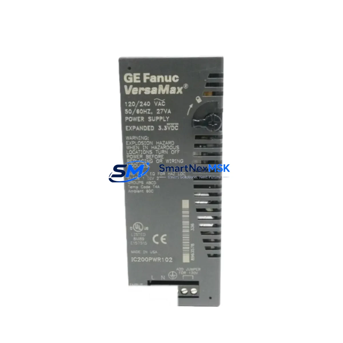
The GE IC200PWR102 is a 24VDC input power supply module engineered for the VersaMax Micro series of programmable logic controllers. As legacy GE Fanuc and early Emerson Automation control systems approach end-of-life, the IC200PWR102 remains one of the most sought-after retrofit components for engineers tasked with modernizing aging production lines without full system replacement. Whether you are restoring a failed power rail, upgrading an undersized supply in an existing control cabinet, or migrating from a discontinued predecessor module, the IC200PWR102 delivers a verified drop-in solution with minimal re-engineering effort.
In retrofit and upgrade projects, the power supply is almost always the first component to be evaluated. The IC200PWR102 provides up to 30W of backplane power, sufficient to support a fully populated VersaMax Micro base with mixed I/O expansion. Engineers replacing older IC200PWR101 units or sourcing alternatives to the IC200PWR001 will find that the IC200PWR102 maintains the same DIN-rail footprint, identical terminal block pitch, and compatible backplane connector geometry — critical factors when working within the physical constraints of an existing control cabinet.
Before installation, confirm the incoming 24VDC supply capacity from your plant power distribution panel or UPS. The IC200PWR102 draws up to 3A at 24VDC under full load; ensure your upstream circuit breaker and cable gauge are rated accordingly. Terminal wiring follows the standard L+, L−, and PE arrangement common across the VersaMax Micro family, so existing field wiring typically requires no modification. If your cabinet also houses an IC200CHS002 or IC200CHS022 base, verify that the backplane slot alignment matches the IC200PWR102 keying before seating the module.
For sites running VersaMax Micro CPUs such as the IC200UDR002, IC200UDR005, or IC200UAL005, the IC200PWR102 is fully compatible without firmware changes. The CPU retains its ladder logic program in non-volatile memory during power cycling, so a controlled power-down for module swap does not risk program loss — provided the CPU battery (IC200ACC001 or equivalent) is in good condition. Always verify battery status before beginning any retrofit procedure.
Upgrade Compatibility Table
| Parameter | IC200PWR102 (This Unit) | Notes / Retrofit Guidance |
|---|---|---|
| Input Voltage | 24VDC (18–30VDC range) | Verify plant supply is within tolerance before swap |
| Backplane Power Output | 30W | Sufficient for full VersaMax Micro base population |
| Terminal Block Pitch | 5.08mm, screw-type | Compatible with existing field wiring; no re-termination needed |
| Backplane Connector | Standard VersaMax Micro keyed connector | Fits IC200CHS002, IC200CHS022 bases |
| DIN Rail Mounting | 35mm DIN rail, standard clip | Drop-in replacement; no cabinet modification required |
| Replaces / Upgrades From | IC200PWR101, IC200PWR001 | Same footprint; confirm terminal labeling before wiring |
| CPU Compatibility | IC200UDR002, IC200UDR005, IC200UAL005 | No firmware update required |
| Communication Protocol Impact | None (power supply only) | Ethernet, serial, and Profibus links unaffected by swap |
| Commissioning Requirement | Power-on self-test only | No re-addressing or re-configuration of I/O modules needed |
| Warranty | 12 Months | Covers manufacturing defects; includes pre-shipment functional test |
Retrofit Planning for Existing Automation Systems
A successful IC200PWR102 retrofit begins with a thorough audit of the existing control system architecture. In a typical VersaMax Micro installation, the power supply feeds not only the CPU but also any installed IC200MDL640 discrete input modules, IC200MDL730 discrete output modules, and IC200ALG320 analog input modules mounted on the same base. Before ordering a replacement, document the total backplane current draw of all installed modules to confirm the IC200PWR102’s 30W budget is not exceeded.
If the existing system includes an IC200ETM001 Ethernet communications module for SRTP or Modbus TCP connectivity, or an IC200PBI001 Profibus DP adapter for integration with a legacy Siemens or ABB field device network, these communication links will remain fully operational through the power supply swap — provided the CPU is brought back online cleanly. Prepare a backup of the CPU program using Proficy Machine Edition or the legacy VersaPro programming software before beginning any physical work. Store the backup on a local engineering workstation and verify the checksum before proceeding.
For cabinets that also house a GE QuickPanel or IC754VSI06CTD operator interface panel, coordinate the HMI shutdown sequence with the power supply replacement. Most QuickPanel units connected via serial RS-232 or RS-485 to the VersaMax Micro CPU will automatically re-establish communication once the CPU completes its restart cycle — typically within 10–15 seconds of power restoration. Verify that HMI screen tags referencing CPU data registers are correctly mapped after restart, particularly for any analog scaling blocks tied to IC200ALG320 or IC200ALG432 modules.
Where the control system includes an IC200PWR102 powering a remote I/O drop connected via IC200BEM002 Bus Expansion Module, treat the remote drop as a separate power domain. Each remote base requires its own power supply assessment; do not assume the main base supply upgrade resolves power issues in remote drops.
Downtime Control During System Migration
Minimizing unplanned downtime is the primary concern in any live production environment. For IC200PWR102 replacements, the recommended approach is a planned maintenance window of 30–60 minutes, which is sufficient for a competent controls engineer to complete the physical swap, verify wiring, restore power, and confirm normal CPU operation.
Before the maintenance window opens, pre-stage the IC200PWR102 on the bench and perform a visual inspection of the terminal block and backplane connector. Confirm the module passes its internal LED self-test when powered independently if a bench supply is available. Label all existing field wiring at the terminal block before disconnection — even if the wiring appears obvious — to eliminate re-termination errors under time pressure.
During the swap, keep the CPU program backup accessible on a laptop with Proficy Machine Edition or VersaPro installed. If the CPU fails to restart cleanly after power restoration — which can occur if the battery-backed RAM has degraded — you will need to reload the program from backup. This scenario adds approximately 10–20 minutes to the maintenance window but does not require any hardware changes beyond the power supply replacement already completed.
After power restoration, verify all I/O module status LEDs, confirm the CPU transitions to RUN mode, and check that the HMI displays live process values before releasing the line back to production. Document the module serial number, installation date, and any wiring deviations from the original drawing for the site maintenance record. All IC200PWR102 units supplied by SMARTNEXMSK are pre-tested prior to shipment and covered by a 12-month warranty against manufacturing defects.
Retrofit Support FAQ
Q: Is the IC200PWR102 a direct drop-in replacement for the IC200PWR101?
A: Yes. The IC200PWR102 shares the same DIN-rail footprint, backplane connector, and terminal block pitch as the IC200PWR101. The primary difference is output power rating. Verify your total backplane load does not exceed 30W before installation. No re-addressing of I/O modules or CPU configuration changes are required.
Q: Will my existing field wiring need to be modified?
A: In the vast majority of retrofit cases, no wiring modification is needed. The IC200PWR102 uses the same L+, L−, and PE terminal arrangement as predecessor VersaMax Micro power supplies. If your existing wiring uses ferrules, inspect them for corrosion before re-termination. Torque terminal screws to the manufacturer specification (typically 0.5–0.6 Nm) to ensure reliable contact.
Q: How do I verify compatibility with my current VersaMax Micro CPU and I/O configuration?
A: Cross-reference your existing CPU model (e.g., IC200UDR002 or IC200UAL005) and all installed I/O modules against the VersaMax Micro System Manual (GFK-1504). Sum the backplane current draw of all modules and confirm the total is within the IC200PWR102’s 30W capacity. If you require assistance with compatibility verification, contact our technical team with your full system BOM.
Q: What does the 12-month warranty cover, and what pre-shipment testing is performed?
A: Every IC200PWR102 unit shipped by SMARTNEXMSK undergoes a functional power-on test confirming correct output voltage, backplane connector integrity, and LED status indication before dispatch. The 12-month warranty covers manufacturing defects and premature failure under normal operating conditions. It does not cover damage resulting from incorrect installation, overvoltage, or physical impact. Warranty claims are processed within 5 business days of receipt of the returned unit.
© 2026 SMARTNEXMSK. All rights reserved.
Original Source: https://smartnexmsk.com
Contact: sales@smartnexmsk.com | +86 18259474341